Method and apparatus to reduce idle link power in a platform

a technology of idle link power and platform, applied in the field of platforms, can solve the problems of high idle power of may not be suitable for high speed serial communication link

Active Publication Date: 2013-01-03
INTEL CORP
View PDF3 Cites 54 Cited by
  • Summary
  • Abstract
  • Description
  • Claims
  • Application Information

AI Technical Summary

Problems solved by technology

However, these high speed serial communication links often require high idle power.
In power sensitive platforms such as hand

Method used


Image

  • Method and apparatus to reduce idle link power in a platform
  • Method and apparatus to reduce idle link power in a platform
  • Method and apparatus to reduce idle link power in a platform

Examples


Embodiment Construction

[0012]Embodiments of the invention described herein are illustrated by way of example and not by way of limitation in the accompanying figures. For simplicity and clarity of illustration, elements illustrated in the figures are not necessarily drawn to scale. For example, the dimensions of some elements may be exaggerated relative to other elements for clarity. Further, where considered appropriate, reference numerals have been repeated among the figures to indicate corresponding or analogous elements.

[0013]Reference in the specification to “one embodiment” or “an embodiment” of the invention means that a particular feature, structure, or characteristic described in connection with the embodiment is included in at least one embodiment of the invention. Thus, the appearances of the phrase “in one embodiment” in various places throughout the specification are not necessarily all referring to the same embodiment.

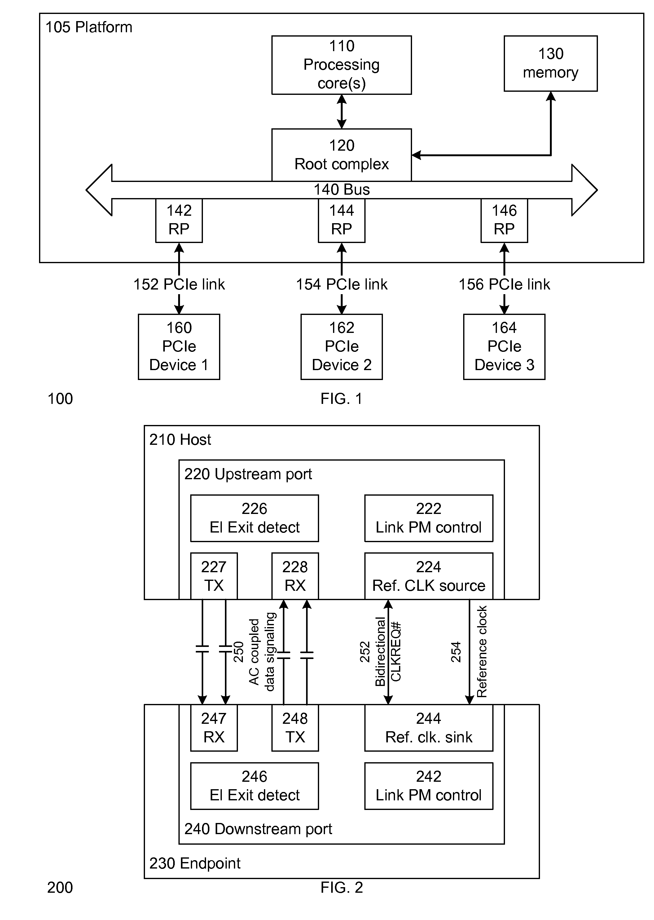
[0014]The terms “upstream” and “downstream” are used to illustrate the dir...


PUM


Abstract

A method and apparatus to reduce the idle link power in a platform. In one embodiment of the invention, the host and its coupled endpoint(s) in the platform each has a low power idle link state that allows disabling of the high speed link circuitry in both the host and its coupled endpoint(s). This allows the platform to reduce its idle power as both the host and its coupled endpoint(s) are able to turn off their high speed link circuitry in one embodiment of the invention.

Description

FIELD OF THE INVENTION[0001]This invention relates to a platform, and more specifically but not exclusively, to a method and apparatus to reduce the idle link power in a platform.BACKGROUND DESCRIPTION[0002]High speed serial communication links are often used in a platform to provide fast data access. However, these high speed serial communication links often require high idle power. In power sensitive platforms such as handheld and tablet computers, high speed serial communication links may not be suitable due to the high idle power requirements.BRIEF DESCRIPTION OF THE DRAWINGS[0003]The features and advantages of embodiments of the invention will become apparent from the following detailed description of the subject matter in which:[0004]FIG. 1 illustrates a block diagram of a platform in accordance with one embodiment of the invention;[0005]FIG. 2 illustrates a block diagram of a host device and an endpoint device in accordance with one embodiment of the invention;[0006]FIG. 3 il...

Claims


Application Information

Patent Timeline
IPC IPC(8): G06F1/32
CPCG06F1/3206G06F1/3278Y02B60/1282Y02B60/126G06F1/3234G06F1/3287Y02D10/00G06F13/14G06F1/32G06F1/325
Inventor DIEFENBAUGH, PAUL S.GOUGH, ROBERT E.BACHRACH, YUVALHUNSAKER, MIKAL C.BEN-TAL, RAFIPARDO, ILANPRAT, GIDEONHARRIMAN, DAVID J.
Owner INTEL CORP
Why Eureka
Try Eureka