Polyaxial bonescrew assembly

a bone screw and polyaxial technology, applied in the field of bone screw assemblies, can solve the problems of limiting the range of motion of the spine, threatening the critical elements, affecting the stability of the head, etc., and achieve the effect of facilitating the retention of the head

Active Publication Date: 2013-01-10
K2M
View PDF36 Cites 72 Cited by
  • Summary
  • Abstract
  • Description
  • Claims
  • Application Information

AI Technical Summary

Problems solved by technology

Genetic or developmental irregularities, trauma, tumors, and disease, however, can result in spinal pathologies that limit the range of motion of the spine and / or threaten the critical elements of the nervous system housed within the spinal column.
However, unforeseen conditions, complications, or other intra-operative events may dictate a change in the previously selected spinal rod, e.g., a different diametered rod may be desired.
As can be appreciated, removing the previously implanted bone screws is undesirable.

Method used


Image

  • Polyaxial bonescrew assembly
  • Polyaxial bonescrew assembly
  • Polyaxial bonescrew assembly

Examples


Embodiment Construction

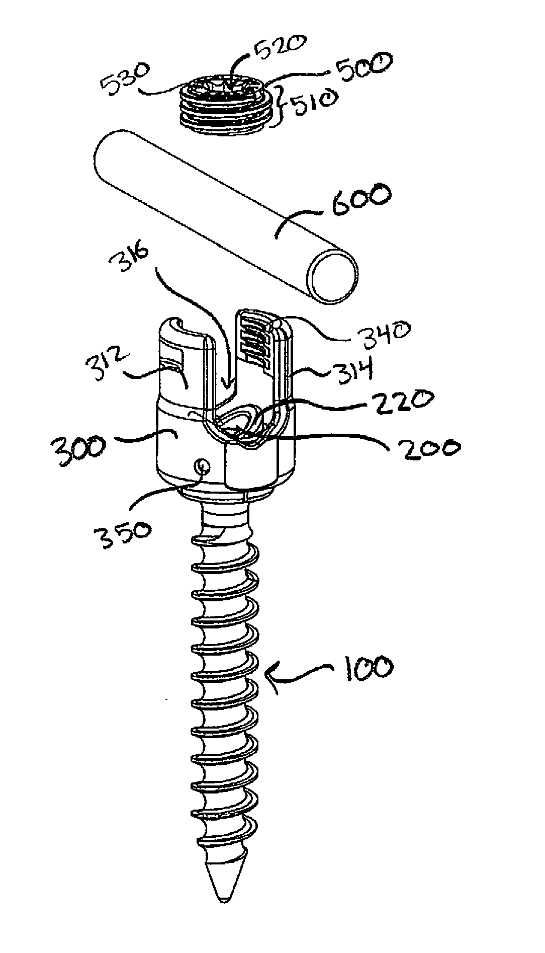
[0053]Various embodiments of the presently disclosed spinal fixation devices and systems will now be described in detail with reference to the drawings, wherein like reference numerals identify similar or identical elements. In the drawings and in the description that follows, the term “proximal,” will refer to the end of a device or system that is closest to the operator, while the term “distal” will refer to the end of the device or system that is farthest from the operator. In addition, the term “cephalad” is used in this application to indicate a direction toward a patient's head, whereas the term “caudad” indicates a direction toward the patient's feet. Further still, for the purposes of this application, the term “medial” indicates a direction toward the middle of the body of the patient, whilst the term “lateral” indicates a direction toward a side of the body of the patient (i.e., away from the middle of the body of the patient). The term “posterior” indicates a direction to...


PUM


Abstract

A bone screw assembly includes a screw, an outer housing, and an inner housing. The screw includes a shank and a head. The outer housing has a proximal end, a distal end, and a passageway extending longitudinally therethrough. The outer housing defines a saddle at the proximal end thereof for receiving at least a portion of a rod therein. The inner housing is positionable within the passageway of the outer housing. The inner housing has a recessed distal portion for receiving the head of the screw therein. The inner housing also includes a proximal surface defining a substantially V-shaped configuration for receiving rods of different diameters therein.

Description

CROSS-REFERENCE TO RELATED APPLICATIONS[0001]This application claims the benefit of, and priority to, U.S. Provisional Patent Application Ser. No. 61 / 307,055 filed on Feb. 23, 2010, and U.S. Provisional Patent Application Ser. No. 61 / 310,056 filed on Mar. 3, 2010, the entire contents of each of which are hereby incorporated by reference herein.BACKGROUND[0002]1. Technical Field[0003]The present disclosure relates bone anchors and, more particularly, to bone screw assemblies for use with surgical rods of varying diameter.[0004]2. Background of Related Art[0005]The adult human spinal column has 24 vertebrae coupled to one another by a tri-joint complex consisting of an anterior disc and the two posterior facet joints. The bones of the spinal column are anatomically categorized as being members of one of four classifications: cervical, thoracic, lumbar, or sacral. The cervical portion of the spine is the top of the spine and includes the first seven vertebrae beginning at the base of t...

Claims


Application Information

Patent Timeline
Patent Type & Authority Applications(United States)
IPC IPC(8): A61B17/86
CPCA61B17/7037A61B17/7004A61B17/7032A61B17/863
Inventor CARBONE, JOHNBOACHIE-ADJEI, OHENEBAMCCLINTOCK, LARRYSTRAUSS, KEVIN R.
Owner K2M
Why Eureka
Try Eureka