Device and method for attaching protective film to and removing protective film from light guide plate

a technology of protective film and light guide plate, which is applied in the direction of optical radiation measurement, photometry using electric radiation detectors, instruments, etc., can solve the problems of low efficiency, easy damage of lgp, and dirty lpg

Inactive Publication Date: 2013-01-17
HON HAI PRECISION IND CO LTD
View PDF16 Cites 22 Cited by
  • Summary
  • Abstract
  • Description
  • Claims
  • Application Information

AI Technical Summary

Problems solved by technology

When the protective film is removed from the LGP, the glue may remain on the surface of the LGP causing stains, which can make the LPG loo...

Method used


Image

  • Device and method for attaching protective film to and removing protective film from light guide plate
  • Device and method for attaching protective film to and removing protective film from light guide plate
  • Device and method for attaching protective film to and removing protective film from light guide plate

Examples


Embodiment Construction

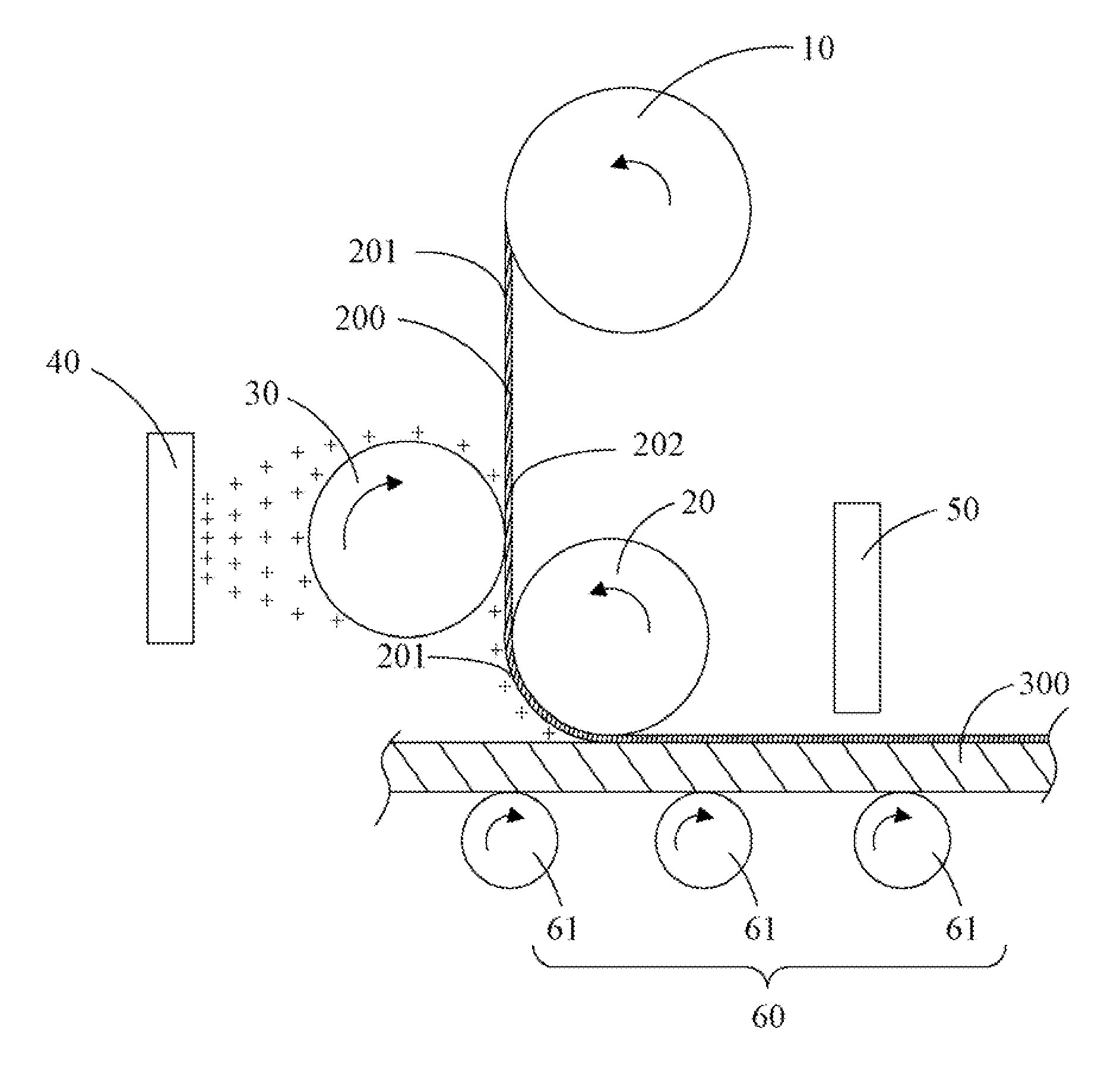
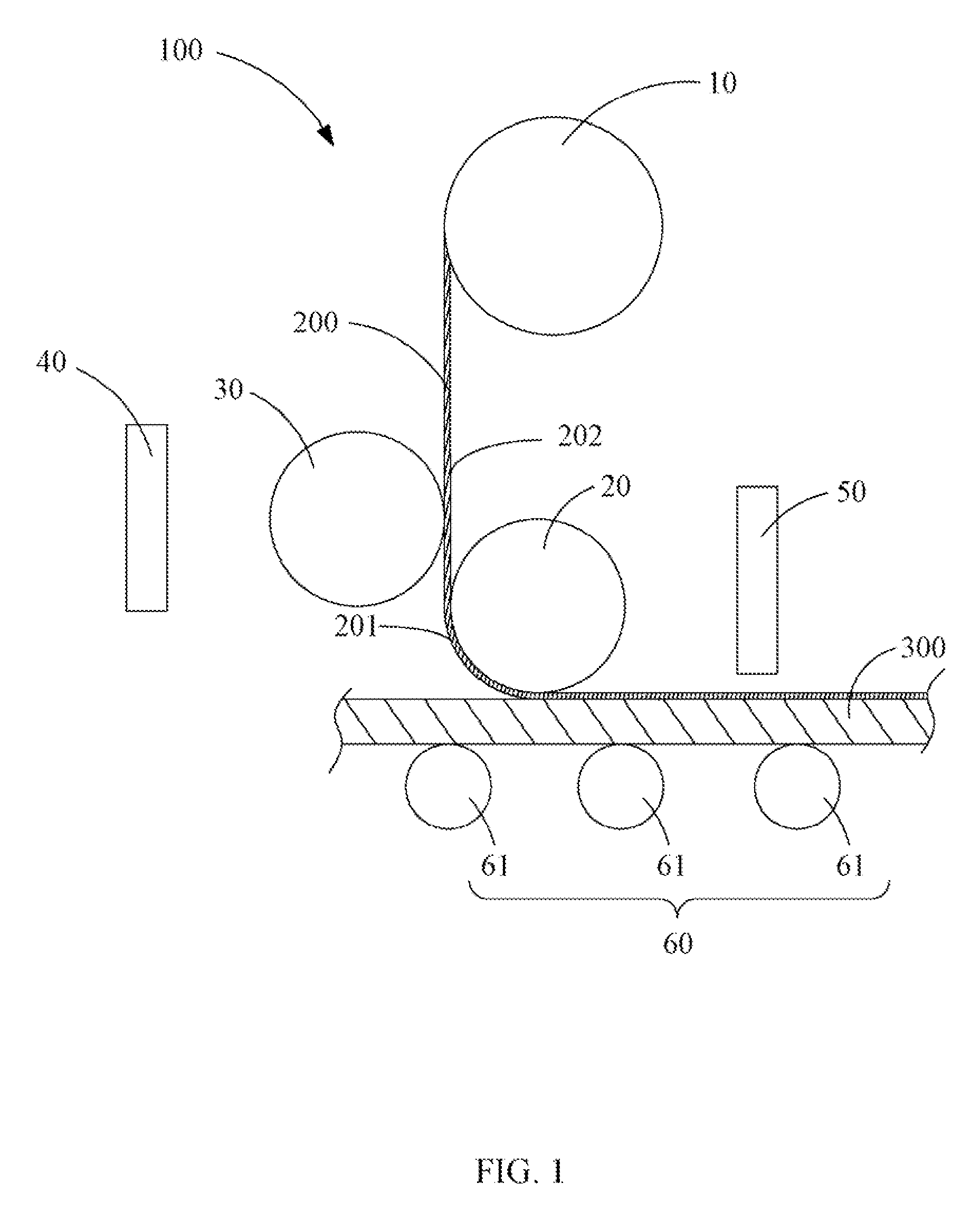
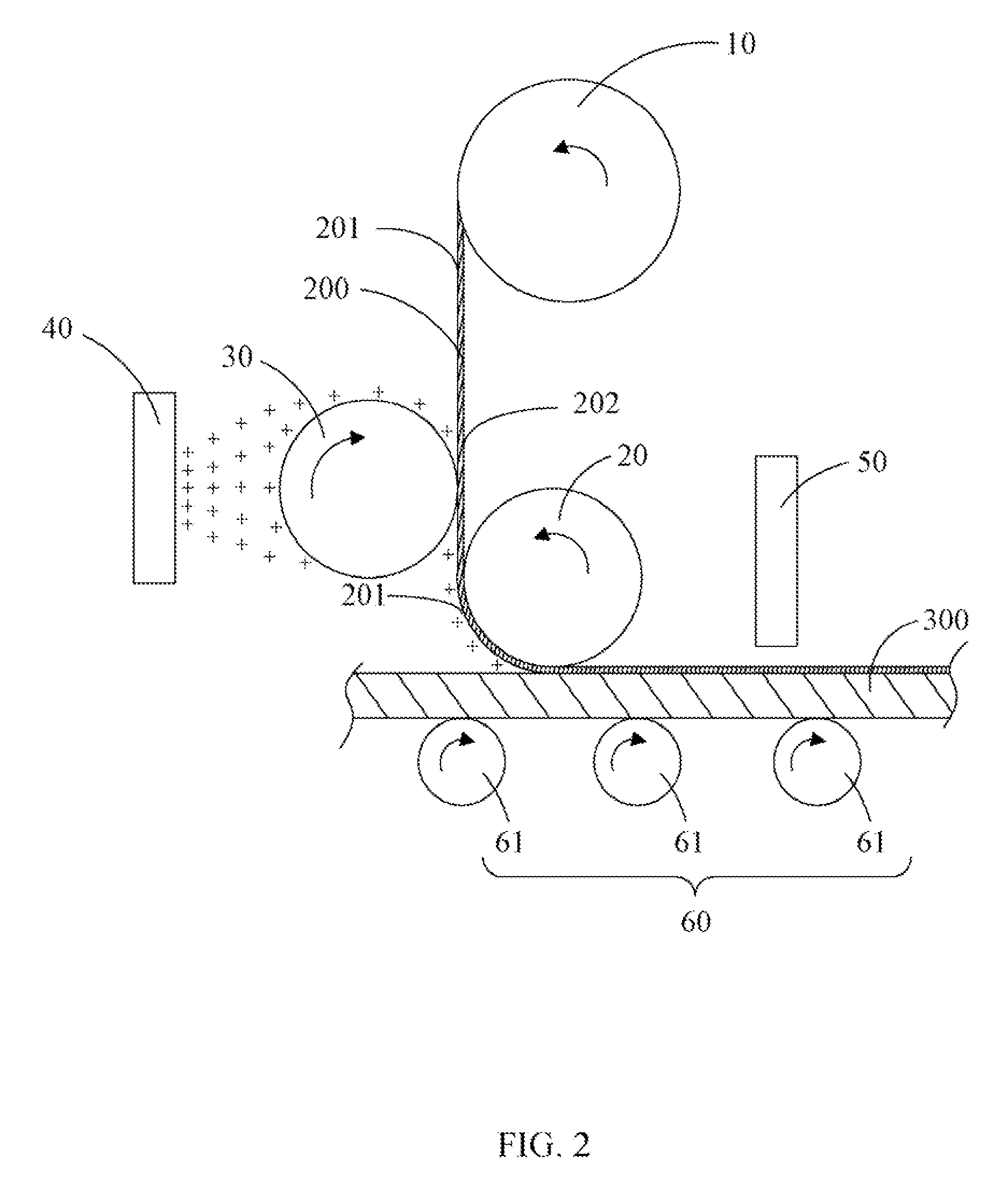
[0009]FIG. 1 is a schematic diagram of a device 100 for attaching a protective film 200 to an LGP 300 and removing the protective film 200 from the LGP 300 in accordance with an exemplary embodiment. The device 100 includes a first roller 10, a second roller 20, a third roller 30, a first fan 40, a second fan 50, and a conveying device 60. The first roller 10 is for rolling up or rolling down the protective film 200 around the first roller 10. The second roller 20 and the third roller 30 respectively contact two surfaces, namely a first surface 201 and a second surface 202, of the protective film 200. The first fan 40 and the third roller 30 are located on one side of the protective film 200. The second fan 50 and the first roller 20 are located on the other side of the protective film 200. The first fan 40 and the second fan 50 are used to generate positive charged ions or negative charged ions according to user's requirement and blow out the generated positive charged ions or nega...


PUM


Abstract

A device includes a first roller to roll down a protective film around the first roller, a conveying device to convey a light guide plate (LGP), and a first fan to generate charged ions and blow out the charged ions. While the rolled-down protective film is being placed onto the LGP being conveyed by the conveying device, the charged ions blown out by the first fan are adhered to a first surface of the protective film to generate static electricity and the first surface of the protective film is attached to the LGP by the static electricity.

Description

BACKGROUND[0001]1. Technical Field[0002]The present disclosure relates to a device and method for attaching a protective film or removing the protective film, particularly to a device and method for attaching the protective film to a light guide plate (LGP) and removing the protective film from the LGP.[0003]2. Description of Related Art[0004]As a precision optical element, the LGP has an important function and needs good protection. After the LGP is manufactured, a protective film is needed to be attached to two surfaces of the LGP to protect the surfaces from being damaged. Generally, the protective film is glued to the LGP. When the protective film is removed from the LGP, the glue may remain on the surface of the LGP causing stains, which can make the LPG look dirty. Furthermore, the protective film should be removed manually from the LPG, thus the LGP may be easily damaged resulting in low efficiency.BRIEF DESCRIPTION OF THE DRAWINGS[0005]The components of the drawings are not ...

Claims


Application Information

Patent Timeline
IPC IPC(8): G01J5/08
CPCG02B6/005G02B6/0093G02B6/0065
Inventor YU, TAI-CHERNGLIN, DA-WEI
Owner HON HAI PRECISION IND CO LTD
Why Eureka
Try Eureka