
Component carrier activation and deactivation using resource assignments

a component carrier and resource assignment technology, applied in the direction of signalling characterisation, power management, wireless commuication services, etc., can solve the problems of resource utilization inefficiency, two pdcchs are required in order to activate a downlink component carrier, and certain error cases may occur in the presence of pdcch loss, so as to reduce signaling overhead and reduce the effect of signaling overhead and robust (de)activation of component carriers

Active Publication Date: 2013-01-17
SUN PATENT TRUST
View PDF9 Cites 24 Cited by
  • Summary
  • Abstract
  • Description
  • Claims
  • Application Information

AI Technical Summary

Benefits of technology

[0110]One object of the invention is to overcome at least one of the described problems. Furthermore, it is another object of the invention to enable efficient and robust (de)activation of component carriers, while minimizing the signaling overhead.

Problems solved by technology

Without CQI information eNodeB doesn't have knowledge about user equipment's downlink channel state and might only select a rather conservative MCS for downlink data transmission which would in turn lead to some resource utilization inefficiency.
As it becomes apparent, the main drawback of the above described component carrier activation method is, that two PDCCHs are required in order to activate a downlink component carrier.
Furthermore due to the fact that the two PDCCHs need to be received / sent simultaneously, certain error cases may occur in the presence of PDCCH loss.
However based on received CQI information eNB erroneously assumes downlink activation has succeeded.
In the second error case when only the uplink PDCCH which requests the aperiodic CQI is lost, eNodeB doesn't acquire CQI and erroneously assumes that downlink activation has failed.

Method used


Image

  • Component carrier activation and deactivation using resource assignments
  • Component carrier activation and deactivation using resource assignments
  • Component carrier activation and deactivation using resource assignments

Examples


Embodiment Construction

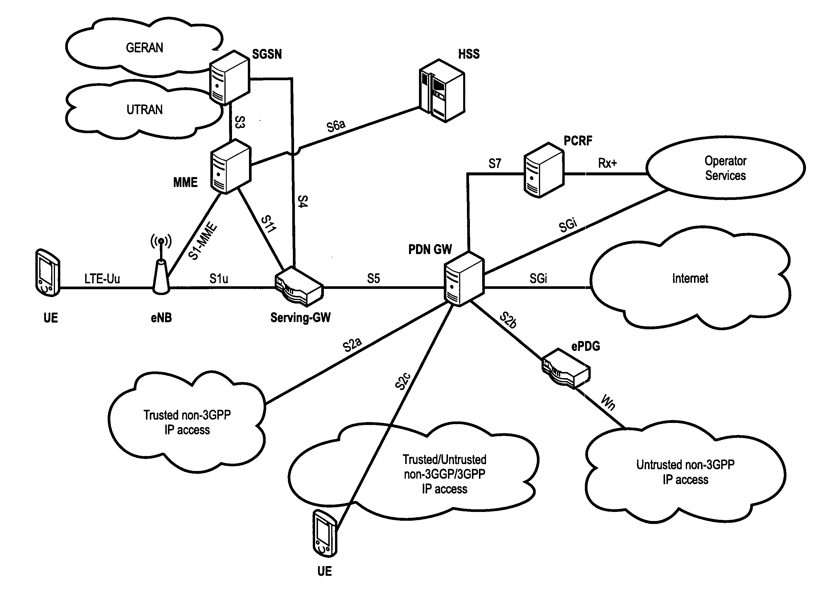
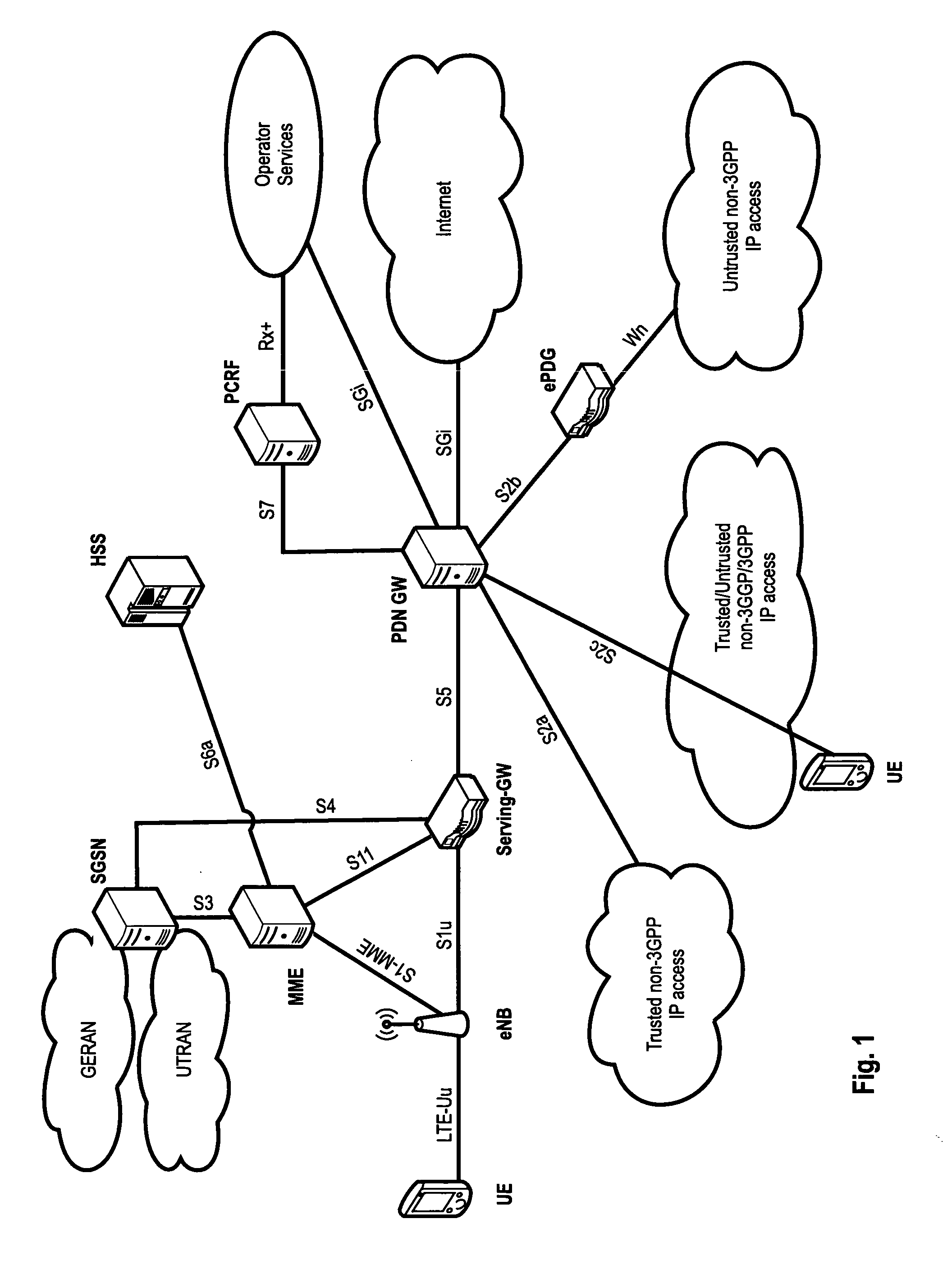
[0170]The following paragraphs will describe various embodiments of the invention. For exemplary purposes only, most of the embodiments are outlined in relation to an orthogonal single-carrier uplink radio access scheme according to 3GPP LTE (Release 8) and LTE-A (Release 10) mobile communication systems discussed in the Technical Background section above. It should be noted that the invention may be advantageously used for example in connection with a mobile communication system such as 3GPP LTE (Release 8) and LTE-A (Release 10) communication systems previously described, but the invention is not limited to its use in this particular exemplary communication network.

[0171]The explanations given in the Technical Background section above are intended to better understand the mostly 3GPP LTE (Release 8) and LTE-A (Release 10) specific exemplary embodiments described herein and should not be understood as limiting the invention to the described specific implementations of processes and...


PUM


Abstract

This invention relates to a proposal of an uplink resource assignment format and a downlink resource assignment format. Furthermore, the invention relates to the use of the new uplink / downlink resource assignments in methods for (de) activation of downlink component carrier (s) configured for a base station and a mobile terminal. To enable efficient and robust (de) activation of component carriers, while minimizing the signaling overhead, the invention proposes a new uplink / downlink resource assignment format that allow the activation / deactivation of individual downlink component carriers configured for a mobile. The new uplink or downlink resource assignment comprises an indication of the activation state of the configured downlink component carriers, i.e. indicate which downlink component carrier (s) is / are to be activated or deactivated. This indication is for example implemented by means of a bit-mask that indicates which of the configured uplink component carriers are to be activated respectively deactivated.

Description

FIELD OF THE INVENTION[0001]This invention relates to the proposal of a new uplink resource assignment format and a new downlink resource assignment format that allow the activation / deactivation of individual downlink component carriers configured for a mobile terminal. Furthermore, the invention relates to the use of the new uplink / downlink resource assignments in methods for (de)activation of downlink component carrier(s) configured for a mobile terminal, a base station and a mobile terminal.TECHNICAL BACKGROUND[0002]Long Term Evolution (LTE)[0003]Third-generation mobile systems (3G) based on WCDMA radio-access technology are being deployed on a broad scale all around the world. A first step in enhancing or evolving this technology entails introducing High-Speed Downlink Packet Access (HSDPA) and an enhanced uplink, also referred to as High Speed Uplink Packet Access (HSUPA), giving a radio-access technology that is highly competitive.[0004]In order to be prepared for further incr...

Claims


Application Information

Patent Timeline
Patent Type & Authority Applications(United States)
IPC IPC(8): H04W84/12
CPCH04L1/0026H04W24/08H04L1/0046H04L1/0061H04L1/0072H04L1/1657H04L5/001H04L5/0053H04L5/0055H04L5/0096H04L5/0098H04L25/03866H04W52/146H04W52/30H04W52/343H04W52/365H04W72/00H04W72/042H04W72/0453H04W52/34Y02B60/50H04L5/0048H04L1/0038H04W72/23H04L5/0057
Inventor LOHR, JOACHIMGOLITSCHEK EDLER VON ELBWART, ALEXANDERFEUERSANGER, MARTIN
Owner SUN PATENT TRUST
Learn More