Synchronization of timing advance and deviation

a timing advance and deviation technology, applied in the field of digital communication systems, can solve the problems of difficult coordination of ta adjustment in the mt and td measurement in the bs to a specific sequential radio frame, radio transmission propagation delay relative, command not to be received, etc., to facilitate a method of geographical positioning

Inactive Publication Date: 2009-08-11
INTERDIGITAL TECH CORP
View PDF27 Cites 9 Cited by
  • Summary
  • Abstract
  • Description
  • Claims
  • Application Information

AI Technical Summary

Benefits of technology

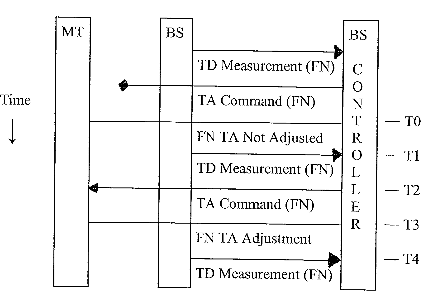
[0033]The invention also facilitates a method of geographically locating a mobile terminal (MT) in a communication system. The method comprises effecting MT timing adjustments by communicating timing advance (TA) command signals to a selected MT, when a measured TD of a signal received by a BS from the selected MT exceeds a TD threshold. The TA command signals including TA data and a Connect Frame Number CFN specifying a particular radio frame. Timing Adjustment of communication data transmissions by the selected MT are made based on the TA data of a TA command signal in the CFN specified radio frame.

Problems solved by technology

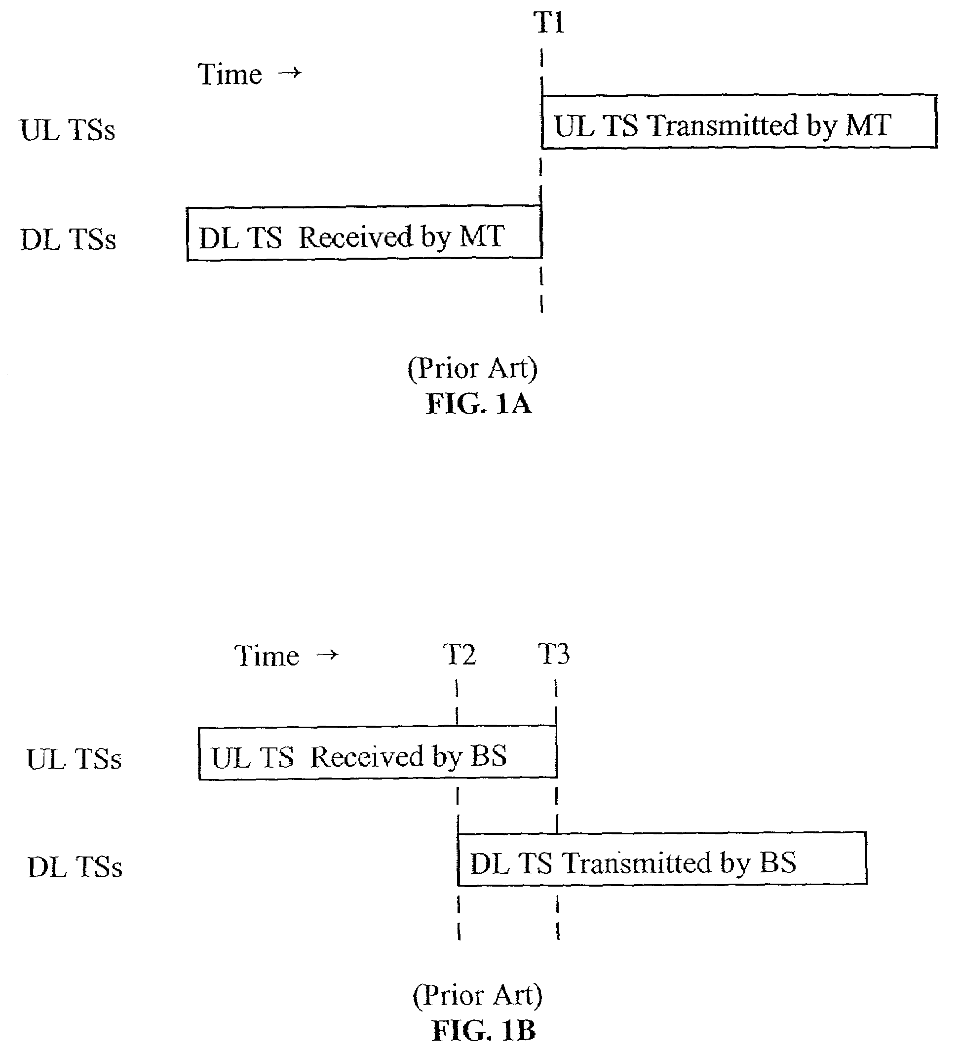
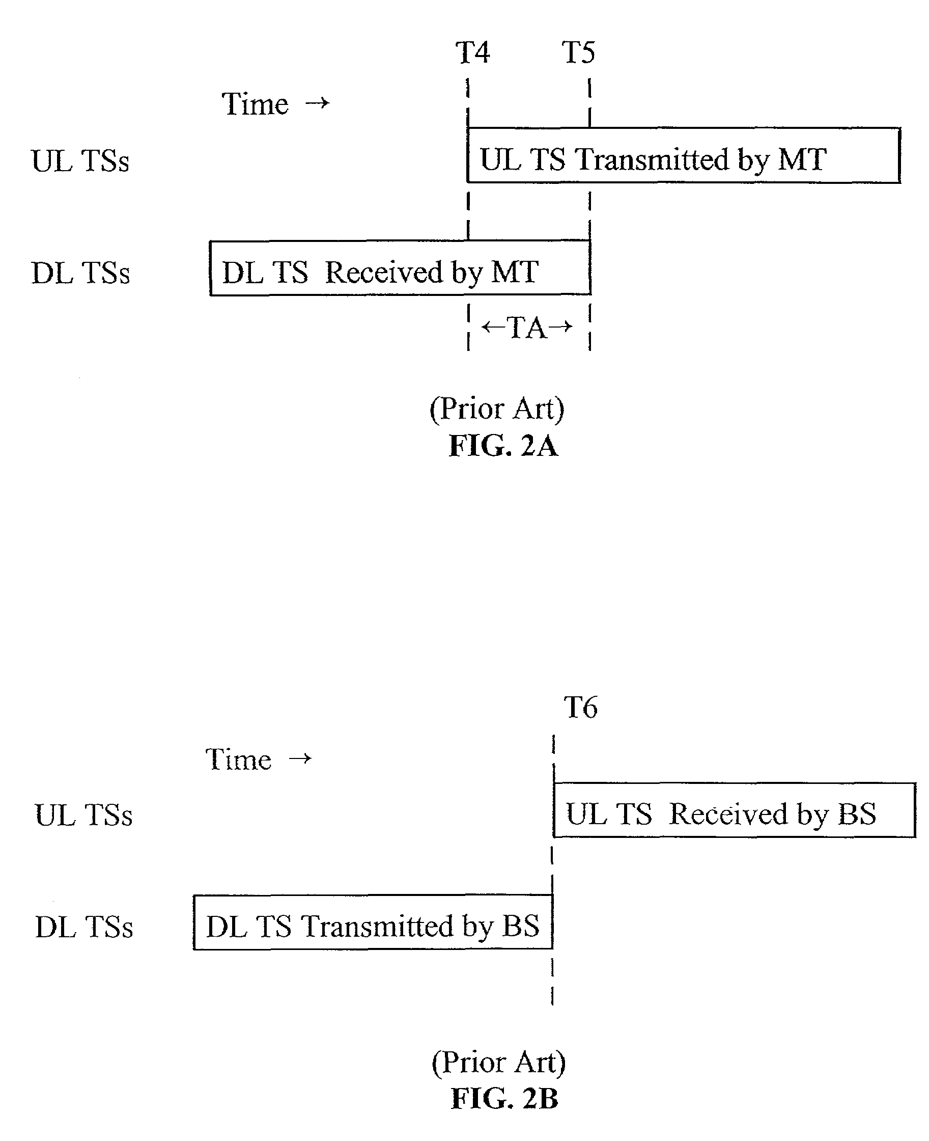
Radio transmissions incur a propagation delay relative to the distance from a transmitter to a receiver.
The logic used to generate TA commands infrequently must also take into account the possibility that radio transmission failures can cause TA commands not to be received by the MT.
The need to coordinate TA adjustment in the MT and TD measurement in the BS to a specific sequential radio frame is difficult since the time of reception and processing in the MT of the BS generated TA command is not known to the BS controller.
However, the period n

Method used


Image

  • Synchronization of timing advance and deviation
  • Synchronization of timing advance and deviation
  • Synchronization of timing advance and deviation

Examples


Embodiment Construction

)

[0046]The embodiments will be described with reference to the drawing figures where like numerals represent like elements throughout.

[0047]Referring to FIG. 9, there is illustrated a communication system 10 comprising a plurality of base stations (BSs) 12 which conduct wireless communication with mobile terminals (MTs) 14. Each BS conducts wireless communications with MTs in a geographic cell, which cell areas normally have some overlap. Where an MT 14 is in an overlap area, bi-directional communication is generally conducted by the BS having the strongest signal link with the MT. Where a second BS begins to have a stronger signal link, “hand off” of the communication occurs. Desired parameters and procedures for effectuating “hand off” are well known in the art.

[0048]In a preferred system such as in accordance with 3G wireless protocols, node Bs 16 are provided in a physical or logical connection with the one or more BSs. A radio network controller (RNC)17, to which the node Bs 16...


PUM


Abstract

A system and method for reducing the latency from timing deviation (TD) measurement to time advance (TA) adjustment. The invention uses a deterministic procedure to coordinate time advance (TA) commands and timing deviation (TD) measurements so that failed transmissions or mobile terminals signal propagation changes can be recognized and corrected much more rapidly. Radio resource efficiency is maximized by minimizing signaling overhead through effectively reducing the frequency of time advance commands. This is accomplished by using TA command signals which include a Connect Frame Number (CFN) to specify particular radio frames for time advance (TA) adjustment. The potential for timing deviation (TD) measurements to be incorrectly processed in conjunction with adjusting a physical reception window and calculating mobile termination location is minimized, without excessive command signaling requirements.

Description

CROSS-REFERENCE TO RELATED APPLICATIONS[0001]This application is a continuation of U.S. application Ser. No. 09 / 826,464, filed Apr. 5, 2001, which claims priority from U.S. Provisional Application No. 60 / 195,087, filed Apr. 6, 2000, which applications are incorporated herein by reference.FIELD OF THE INVENTION[0002]The present invention relates generally to digital communication systems. More specifically, the invention relates to a system and method for synchronizing uplink and downlink transmissions for time division duplex and time division multiple access protocols to compensate for radio propagation delays. As an additional benefit, the systems facilitate geographic location of mobile terminals.BACKGROUND OF THE INVENTION[0003]In the proposed 3rd generation (3G) wireless protocols, time division duplex (TDD) and time division multiple access (TDMA) methods divide an allocated radio spectrum into repetitive time periods known as radio frames which are uniquely identified by a se...

Claims


Application Information

Patent Timeline
IPC IPC(8): H04J3/06H04J3/00H04B7/26H04W56/00H04W92/10
CPCH04B7/2681H04W56/001H04W56/0045H04W56/0005H04J3/0682H04W56/00H04W92/10H04W16/14
Inventor TERRY, STEPHEN E.
Owner INTERDIGITAL TECH CORP
Why Eureka
Try Eureka