Real-time inspection guidance of triangulation scanner

a scanner and real-time inspection technology, applied in the field of triangulation scanners, can solve the problem of extra effort required to adapt the scanner to measure the surface,

Active Publication Date: 2015-02-26
FARO TECH INC
View PDF4 Cites 42 Cited by
  • Summary
  • Abstract
  • Description
  • Claims
  • Application Information

AI Technical Summary

Benefits of technology

[0009]Another embodiment of the invention includes an apparatus for measuring three-dimensional (3D) coordinates of a surface of an object, the apparatus having a structured light scanner comprising a processor, a projector, and a camera. The processor is responsive to executable instructions which when executed by the processor facilitates the above-stated method.

Problems solved by technology

When the scanner is positioned manually or under computer control in a motorized system, extra effort is required to adapt the scanner to measure the surfaces of different objects.

Method used


Image

  • Real-time inspection guidance of triangulation scanner
  • Real-time inspection guidance of triangulation scanner
  • Real-time inspection guidance of triangulation scanner

Examples


Embodiment Construction

[0021]As explained hereinabove, a triangulation scanner that projects a pattern of light in an area, a (2D) pattern, onto an object surface is often referred to as a structured light scanner. A discussion of structured light scanners is given in U.S. Published Application 2012 / 0262550 (Publication '550) to Bridges, the entire contents of which are incorporated by reference herein.

[0022]General Discussion of Structured Light Scanners and Triangulation

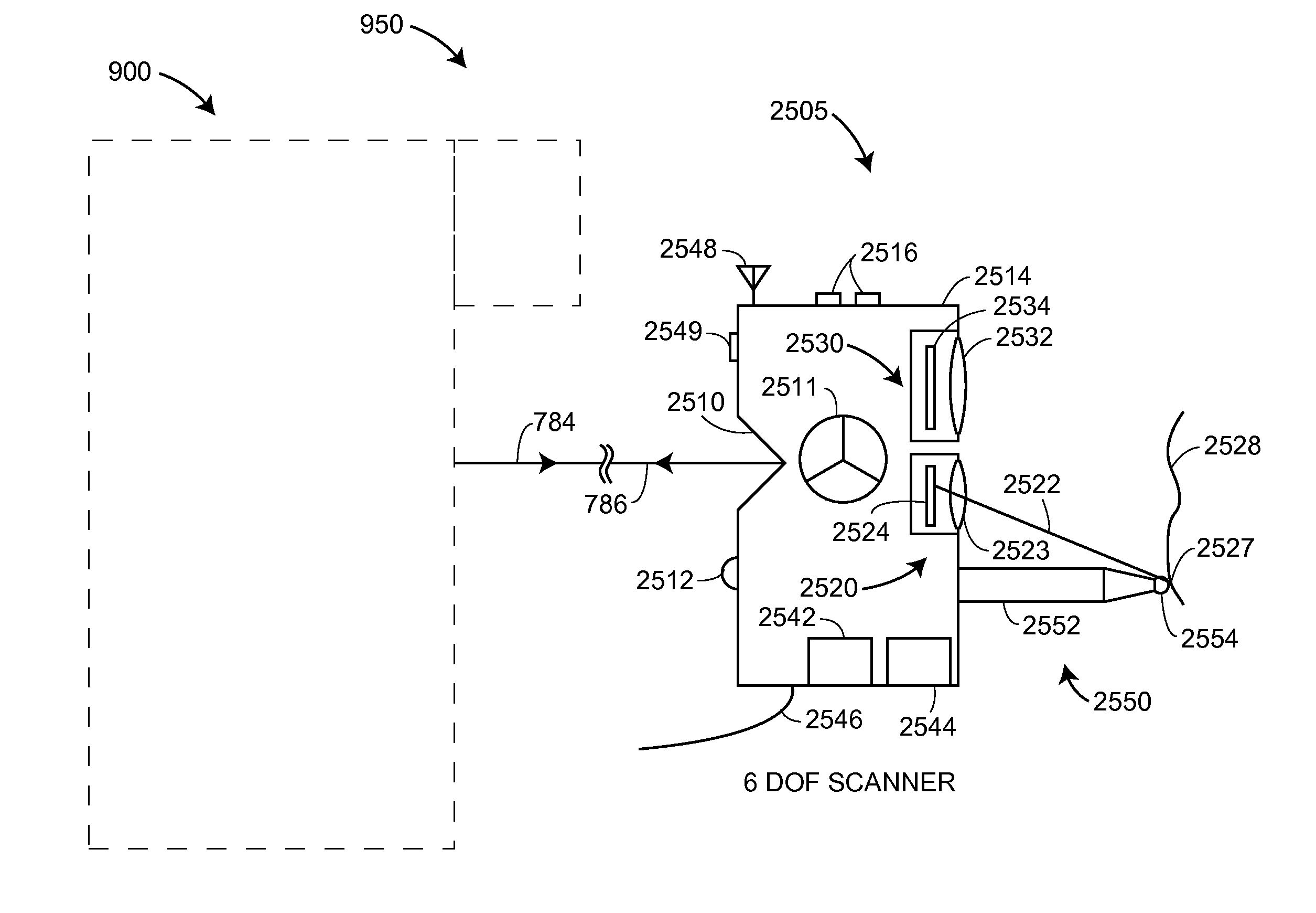
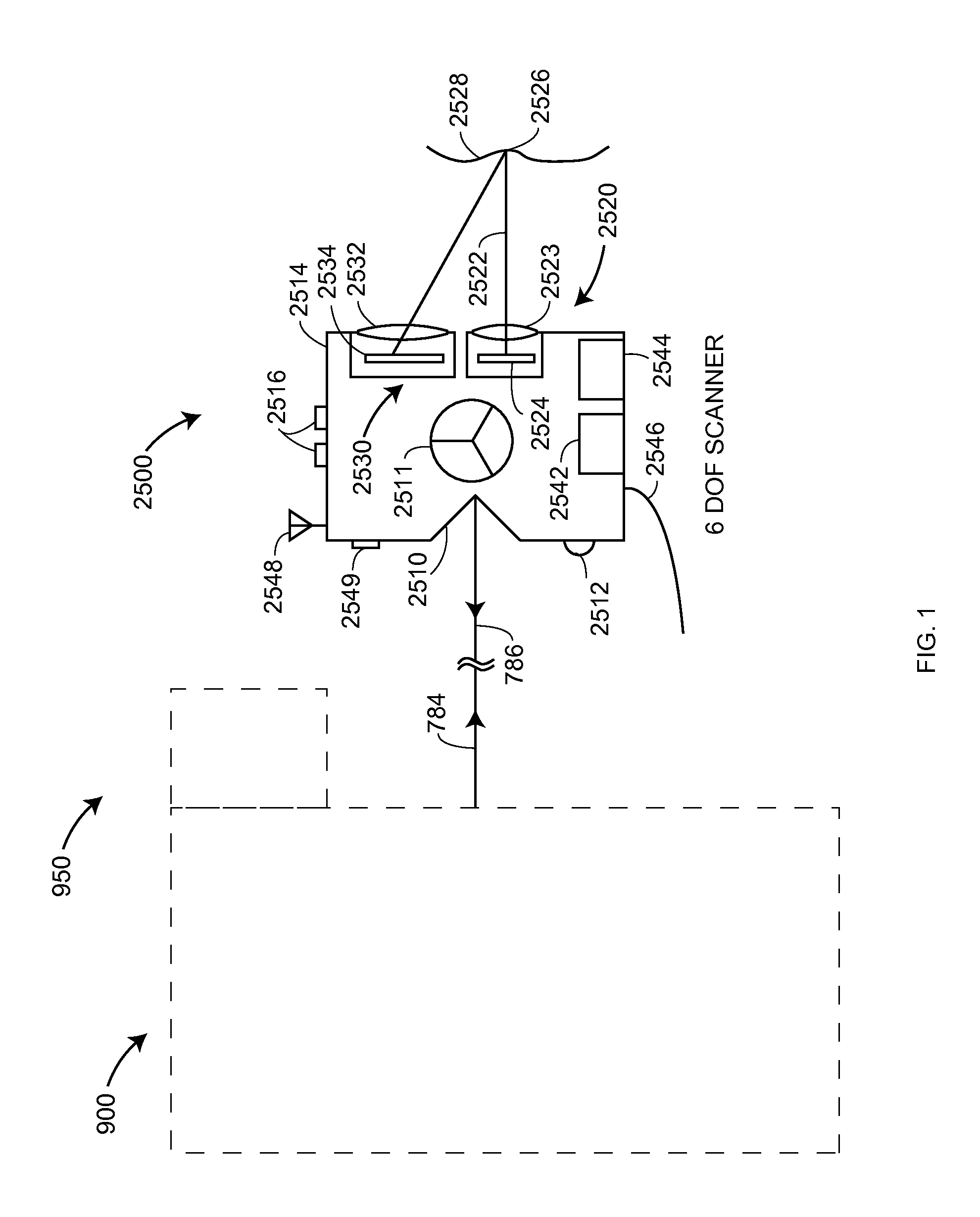
[0023]FIG. 1 shows an embodiment of a six-DOF scanner 2500 used in conjunction with an optoelectronic system 900 and a locator camera system 950. The six-DOF scanner 2500 may also be referred to as a “target scanner.” The optoelectronic system 900 and the locator camera system 950 were discussed in reference to FIG. 13 in Publication '550. In another embodiment, the optoelectronic system 900 is replaced by the optoelectronic system that uses two or more wavelengths of light. The six-DOF scanner 2500 includes a body 2514, one or more retr...


PUM


Abstract

A processor and projector images a coded projector pattern of light on a portion of an object providing a first coded surface pattern of light, images a first sequential projector pattern of light on another portion of the object providing a first sequential surface pattern of light, and images a second sequential projector pattern of light on the other portion providing a second sequential surface pattern of light. A camera forms a first coded image of the first coded surface pattern of light and generates a first coded array, forms a first sequential image of the first sequential surface pattern of light and generates a first sequential array, forms a second sequential image of the second sequential surface pattern of light and generates a second sequential array. The processor determines a correspondence between the camera and projector, and measures three-dimensional coordinates of the object.

Description

CROSS REFERENCE TO RELATED APPLICATIONS[0001]This application claims the benefit of U.S. Provisional Application Ser. No. 61 / 868,124, filed August 21, 2013, which is incorporated herein by reference in its entirety.BACKGROUND[0002]The present disclosure relates to a triangulation scanner that measures three-dimensional (3D) coordinates.[0003]A triangulation scanner measures 3D coordinates of a surface of an object by projecting a pattern of light onto the surface, imaging the light pattern with a camera, and performing a triangulation calculation to determine the 3D coordinates of points on the surface. A triangulation scanner includes a projector and a camera separated from one another by a baseline distance. The projector includes an illuminated pattern and a projector lens, and the camera includes a lens and a photosensitive array.[0004]A category of triangulation scanner is a structured light scanner that projects light over an area. This type of scanner is distinguished from a ...

Claims


Application Information

Patent Timeline
Patent Type & Authority Applications(United States)
IPC IPC(8): G06T7/00H04N5/225G06K9/00
CPCG06T7/0044G06T2207/10004H04N5/2256G06K9/00664G01B11/2513G01B11/25G06T1/0007G06V20/10H04N23/56
Inventor ZHANG, CHI
Owner FARO TECH INC
Why Eureka
Try Eureka