
Wire access line drum assembly

Active Publication Date: 2013-01-24
SYNERGY IND LP
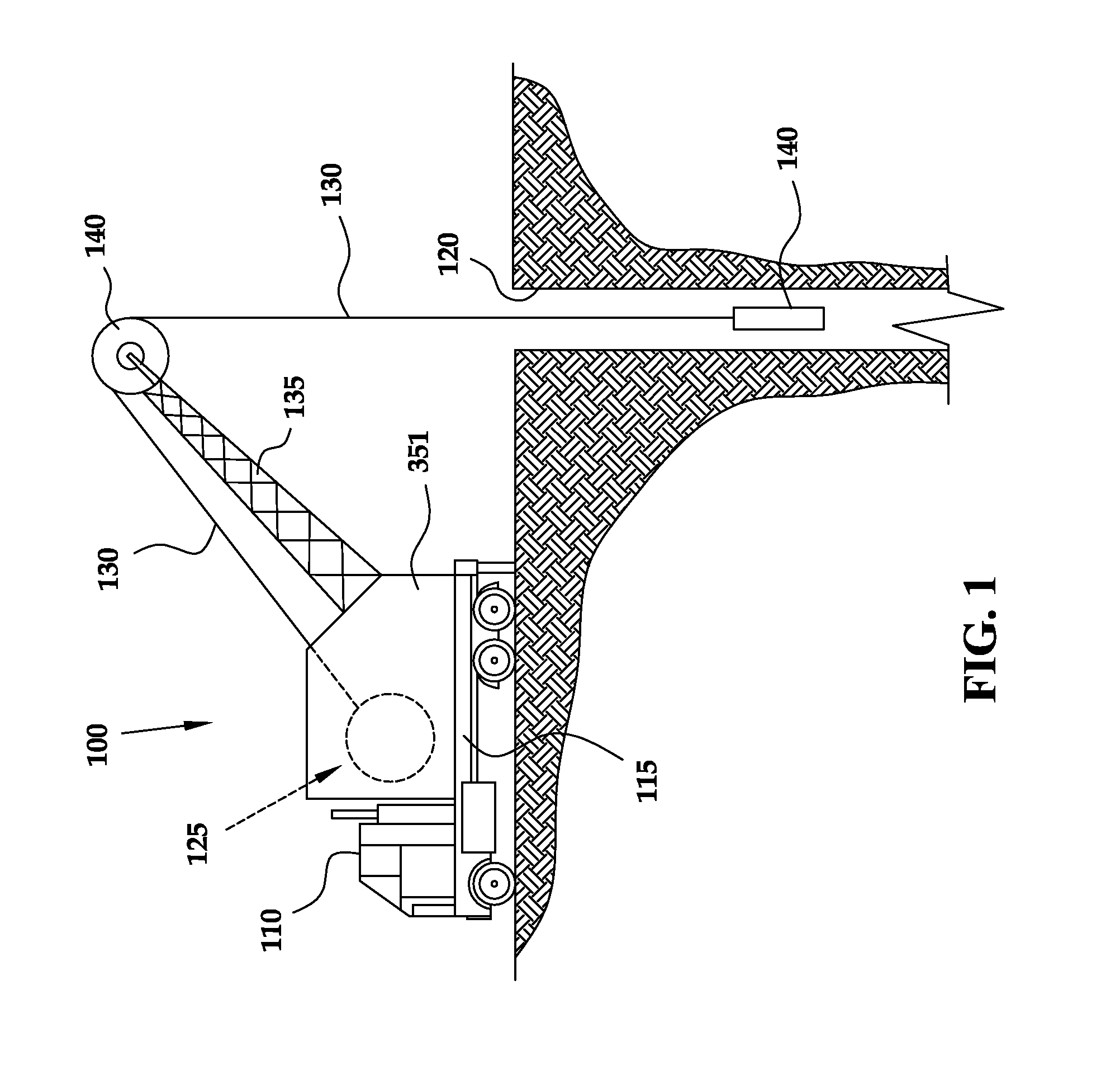
View PDF26 Cites 6 Cited by
  • Summary
  • Abstract
  • Description
  • Claims
  • Application Information

AI Technical Summary

Benefits of technology

The patent describes a wire access line drum assembly and a drum storage system. The wire access line drum assembly includes a tubular drum with first and second end portions and a shaft. The drum storage system includes a rack that can hold multiple wire access line drums, which have their wire access lines pre-spooled on them. These systems allow for easy transportation and retrieval of wire access lines from a job site. The technical effect of this patent is to provide a more convenient and efficient way to handle wire access lines in construction and engineering projects.

Problems solved by technology

Drilling, completing and producing hydrocarbon and other wells are generally complicated and expensive operations.
Accordingly, for the well access line to extend to a desired depth within the well, it may need to be several thousand feet in length, and thus will have a very substantial weight.
Given the substantial length and weight of some well access lines that are stored on the drum assembly, it should be appreciated that the well access line may exhibit substantial forces on the drum assembly, which can lead to undesirable deformation or even crushing of the drum.
During these types of procedures, the drum assembly can be subjected to a significant amount of strain and tension from the load placed thereon by the line.
For example, withdrawing the well access line from the well places a significant amount of stress on the drum assembly.
Furthermore, there may be a significant amount of fluid resistance to the tool being removed, especially if the rate of removal is relatively high.
The cumulative effects of such tension may lead to undesirable deformation or even crushing of the drum assembly.
Unfortunately, replacing the drum assembly can be prohibitively expensive, in some cases costing $80,000 or more.
These rising forces associated with modern wells have dramatically reduced the life expectancy of a conventional drum assembly, and thus, have significantly increased operating costs.

Method used


Image

  • Wire access line drum assembly
  • Wire access line drum assembly
  • Wire access line drum assembly

Examples


Embodiment Construction

[0023]One or more specific embodiments of the disclosed subject matter will be described below. It is specifically intended that the disclosed subject matter not be limited to the embodiments and illustrations contained herein, but include modified forms of those embodiments including portions of the embodiments and combinations of elements of different embodiments as come within the scope of the following claims. It should be appreciated that in the development of any such actual implementation, as in any engineering or design project, numerous implementation-specific decisions may be made to achieve the developers' specific goals, such as compliance with system-related and business related constraints, which may vary from one implementation to another. Moreover, it should be appreciated that such a development effort might be complex and time consuming, but may nevertheless be a routine undertaking of design, fabrication, and manufacture for those of ordinary skill having the bene...


PUM


Abstract

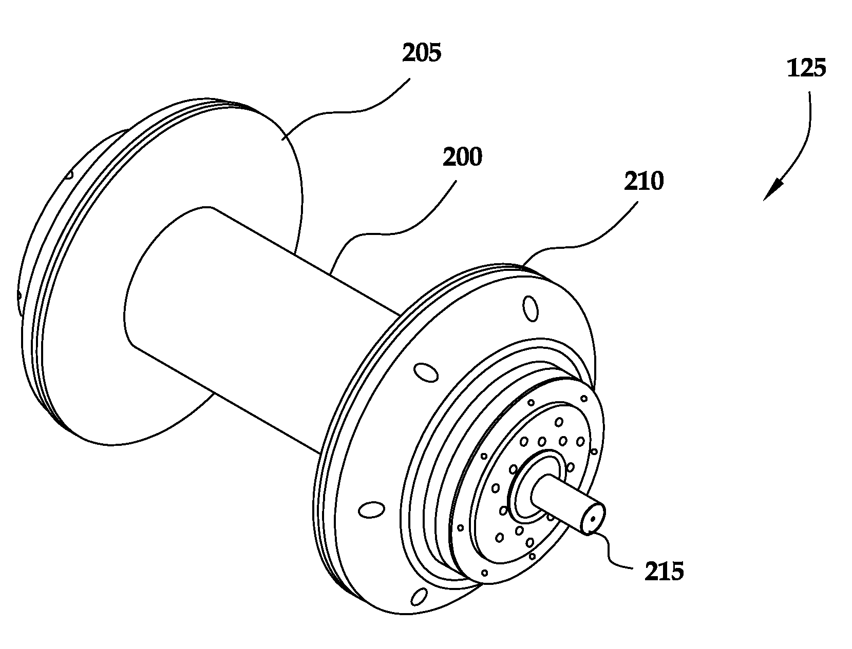
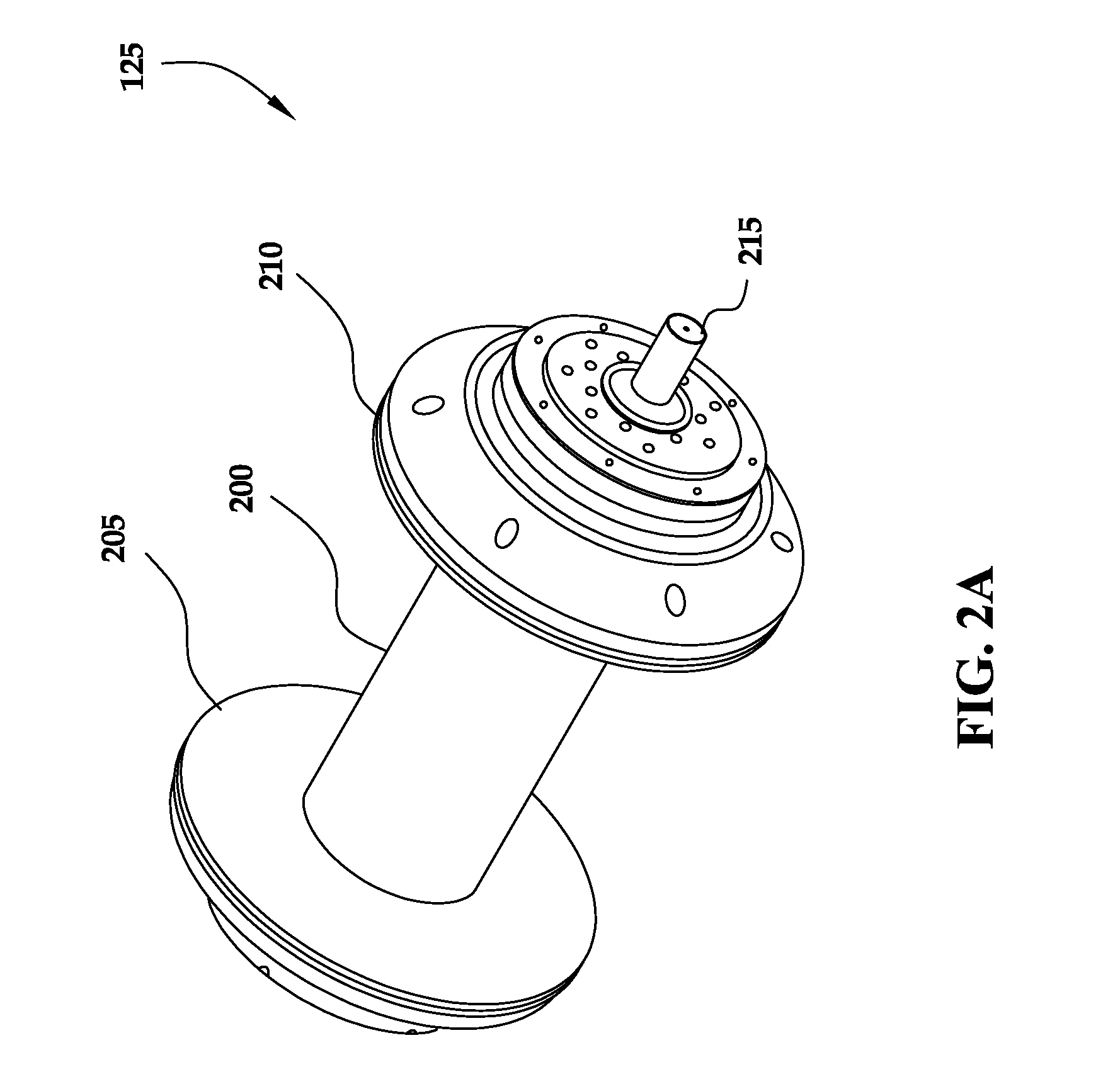
One aspect of the disclosed subject matter is seen in a wire access line drum assembly, comprising a tubular drum, first and second end portions, and a shaft. The tubular drum includes a first end, a second end, and an inner diameter of a first preselected size. The first and second end portions are coupled to the first and second ends of the tubular drum, and the shaft extends at least partially within the tubular drum. The shaft has an outer diameter of a second preselected size substantially similar to the first preselected size. Another aspect of the disclosed subject matter is seen in a drum storage system. The drum storage system is comprised of a plurality of wire access line drums and a rack. The plurality of wire access line drums each have a wire access line pre-spooled thereon, and the rack is designed to receive the plurality of wire access line drums in a configuration to permit one or more of the wire access lines to be retrieved from the rack and transported to a job site.

Description

CROSS-REFERENCE TO RELATED APPLICATIONS[0001]Not applicable.BACKGROUND[0002]The disclosed subject matter relates generally to well access lines and, more particularly, to a drum assembly for storing and deploying a well access line, wherein the drum assembly resists undesirable deformation and / or crushing when employed in a high-stress environment.[0003]Drilling, completing and producing hydrocarbon and other wells are generally complicated and expensive operations. Accordingly, monitoring the condition of the well and performing routine maintenance on the well are useful in maintaining its proper health so as to extend the useful life of, and production from, the well.[0004]Such monitoring and maintenance of the well is generally provided by a well access line stored on and deployed from a drum assembly positioned adjacent the wellbore. The well access line may take on any of a variety of forms, such as a coiled tubing line capable of delivering a fluid therethrough and into the we...

Claims


Application Information

Patent Timeline
IPC IPC(8): B65H75/14A47F7/00B65H75/18
CPCB66D1/30B66D1/34B65H75/42B65H75/14B65H75/08
Inventor NERO, KENNETH MICHAELCORAM, WALTER THOMASVALENTINE, WILLIAM RAYMONDLEWIS, KEVIN BRYAN
Owner SYNERGY IND LP
Features
  • Generate Ideas
  • Intellectual Property
  • Life Sciences
  • Materials
  • Tech Scout
  • Unparalleled Data Quality
  • Higher Quality Content
  • 60% Fewer Hallucinations
Learn More