Layout method of sub-pixel renderings

a technology of subpixels and renderings, applied in the field of layout methods of subpixel renderings, can solve problems such as the inability to implement 3d images, and achieve the effect of improving image resolution and display quality

Active Publication Date: 2013-01-24
AU OPTRONICS CORP
View PDF6 Cites 19 Cited by
  • Summary
  • Abstract
  • Description
  • Claims
  • Application Information

AI Technical Summary

Benefits of technology

[0007]One of the objectives of the present invention is to provide a method for dividing a pixel rendering into a first sub-pixel rendering corresponding to a left-eye image and a second sub-pixel rendering corresponding to a right-eye image when displaying a stereo image, in order to improve image resolution and display quality.

Problems solved by technology

In both the left-eye image and the right-eye image, however, a single row will lack certain colors, and thus a 3D image is unable to be implemented.

Method used


Image

  • Layout method of sub-pixel renderings
  • Layout method of sub-pixel renderings
  • Layout method of sub-pixel renderings

Examples


first embodiment

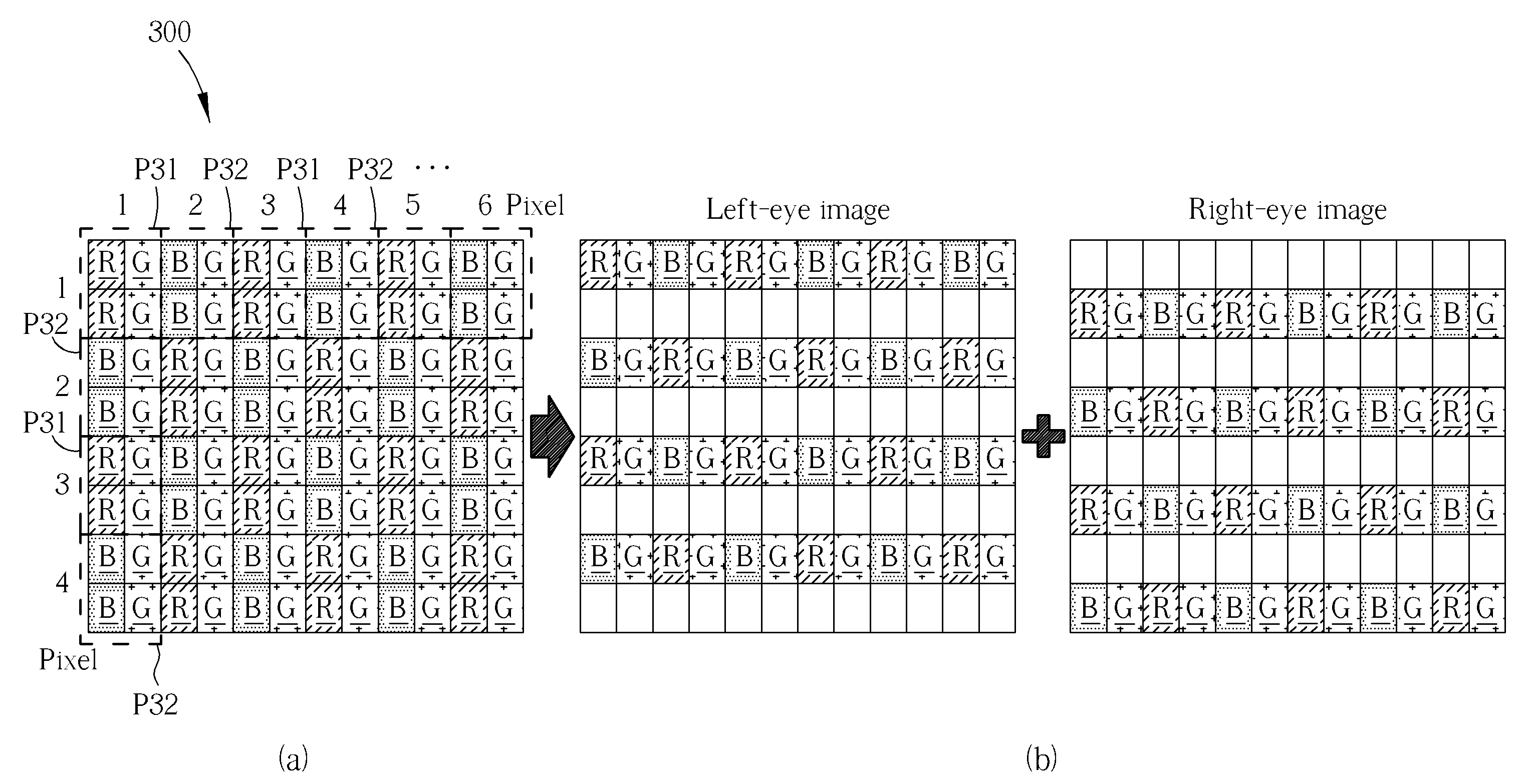
[0033]In the following paragraphs, the embodiments of FIG. 3 to FIG. 8 are used for illustrating the layout method of a sub-pixel rendering shown in FIG. 2. Please refer to FIG. 3, which is a diagram showing a pixel rendering 300 by using a layout method of a sub-pixel rendering according to the present invention. FIG. 3 includes sub-diagrams FIG. 3(a) and FIG. 3(b). As shown in FIG. 3(a), each pixel of the pixel rendering 300 located in each row includes two sub-pixels. In addition, the pixel rendering 300 includes a plurality of first sub-pixel groups P31 and a plurality of second sub-pixel groups P32, wherein the first sub-pixel group P31 and the second sub-pixel group P32 are in an interlaced arrangement. For example, each row of each of the first sub-pixel groups P31 includes an R sub-pixel and a G sub-pixel, and each row of each of the second sub-pixel groups P32 includes a B sub-pixel and a G sub-pixel.

[0034]Please note that, as shown in FIG. 3(b), when displaying a stereo im...

second embodiment

[0035]Please refer to FIG. 4. FIG. 4 (including sub-diagrams FIG. 4(a) and FIG. 4(b)) is a diagram showing a pixel rendering 400 by using a layout method of a sub-pixel rendering according to the present invention. The architecture of the pixel rendering 400 shown in FIG. 4 is similar to that of the pixel rendering 300 shown in FIG. 3, The difference between them is that: in FIG. 3, the pixel rendering 300 is divided into a first sub-pixel rendering corresponding to a left-eye image and a second sub-pixel rendering corresponding to a right-eye image with a row-interlaced arrangement; in FIG. 4, the pixel rendering 400 is divided into a first sub-pixel rendering corresponding to a left-eye image and a second sub-pixel rendering corresponding to a right-eye image with a column-interlaced arrangement. Those skilled in the art can readily understand the arrangement rule of the pixel rendering 400 based on the description of the pixel rendering 300, and further description is omitted her...

third embodiment

[0036]Please refer to FIG. 5, which is a diagram showing a pixel rendering 500 by using a layout method of a sub-pixel rendering according to the present invention. FIG. 5 includes sub-diagrams FIG. 5(a) and FIG. 5(b). As shown in FIG. 5(a), each pixel of the pixel rendering 500 located in each row includes two sub-pixels. In addition, the pixel rendering 500 includes a plurality of first sub-pixel groups P51 and a plurality of second sub-pixel groups P52, wherein the first sub-pixel group P51 and the second sub-pixel group P52 are in an interlaced arrangement. For example, each row of each of the first sub-pixel groups P51 sequentially includes R, G, B, R, G and B sub-pixels, and each row of each of the second sub-pixel groups P52 sequentially includes B, G, R, B, G, and R sub-pixels.

[0037]Please note that, as shown in FIG. 5(b), when displaying a stereo image, each pixel is divided into four sub-pixels in order to generate a first sub-pixel rendering as a left-eye image and a seco...


PUM


Abstract

A layout method of sub-pixel renderings includes the following steps: providing an RGB pixel rendering, wherein each pixel of the RGB pixel rendering includes a plurality of sub-pixels, and the plurality of sub-pixels have different colors from each other; and when displaying a stereo image, dividing the RGB pixel rendering into a first sub-pixel rendering corresponding to a left-eye image and a second sub-pixel rendering corresponding to a right-eye image; wherein at least one of each row and each column of the first sub-pixel rendering includes R, G, and B sub-pixels, and at least one of each row and each column of the second sub-pixel rendering includes R, G, and B sub-pixels.

Description

BACKGROUND OF THE INVENTION[0001]1. Field of the Invention[0002]The present disclosure relates to a layout method of sub-pixel renderings, and more particularly, to a layout method for dividing a pixel rendering into a first sub-pixel rendering corresponding to a left-eye image and a second sub-pixel rendering corresponding to a right-eye image when displaying a stereo image.[0003]2. Description of the Prior Art[0004]In the prior art, when automatically generating a stereo image, a left-eye image and a right-eye image are displayed in liquid crystal layers in an interlaced format. As a result, the left eye of a viewer can only see the left-eye image and the right eye of the viewer can only see the right-eye image so as to generate a parallax effect which makes the viewer automatically sense a stereo image. This means, however, that a horizontal resolution (or a vertical resolution) of the stereo image which the viewer senses is only half of its original pixel rendering. In other wor...

Claims


Application Information

Patent Timeline
Patent Type & Authority Applications(United States)
IPC IPC(8): G06T15/00
CPCH04N13/0422G09G2300/0452G09G2340/0457G09G2300/0443H04N13/0037G09G3/3208H04N13/15H04N13/324
Inventor YANG, HSUEH-YENCHU, SHANG-CHIEHLIN, HONG-SHEN
Owner AU OPTRONICS CORP
Why Eureka
Try Eureka