
Light shielding plate of outdoor LED lighting device

a technology of led lighting and shielding plate, which is applied in the direction of fixed installation, lighting and heating apparatus, lighting support devices, etc., can solve the problems of residents being unable to see, unable to meet the needs of residents,

Inactive Publication Date: 2013-01-24
EXCELLENCE OPTO INC
View PDF2 Cites 38 Cited by
  • Summary
  • Abstract
  • Description
  • Claims
  • Application Information

AI Technical Summary

Benefits of technology

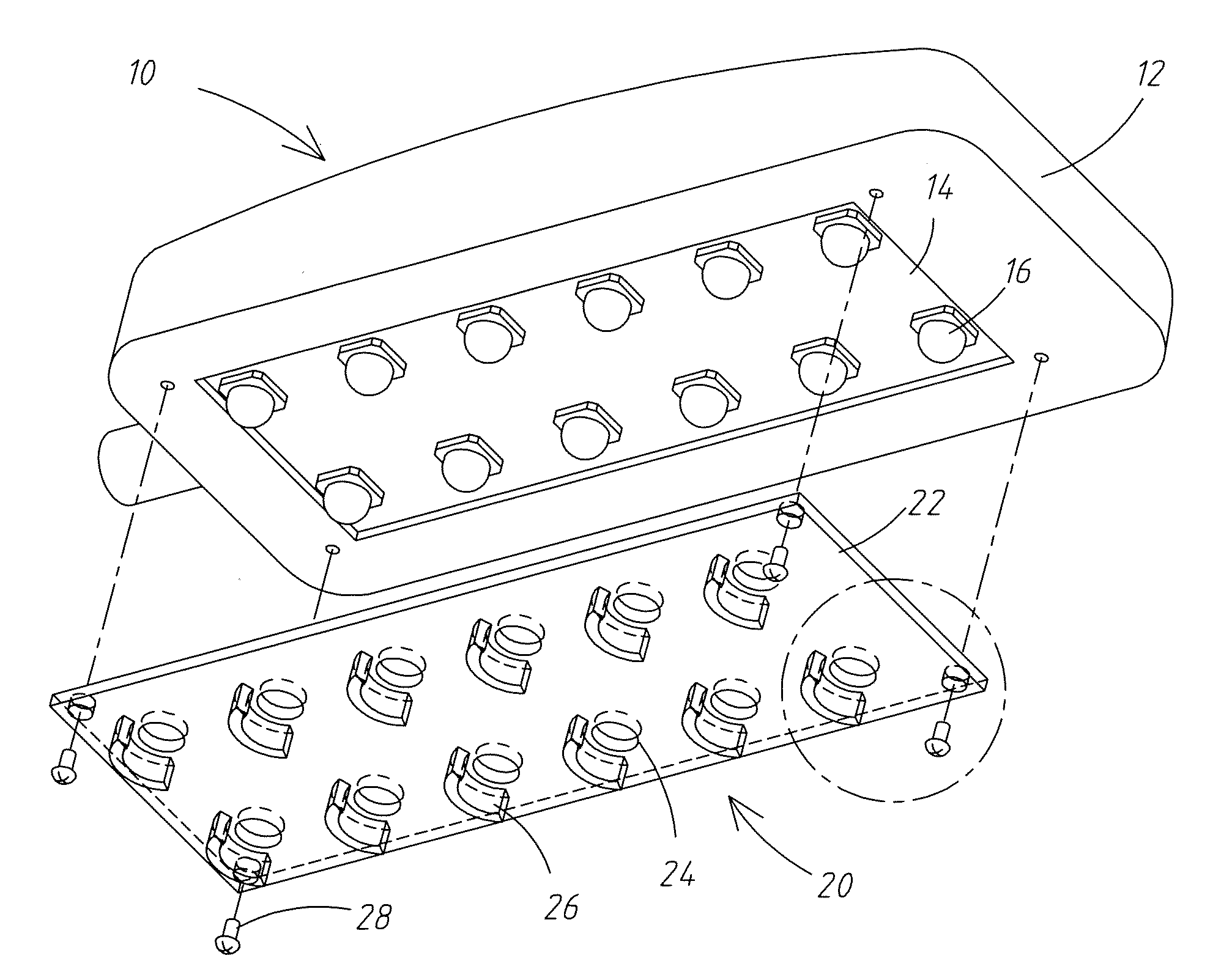
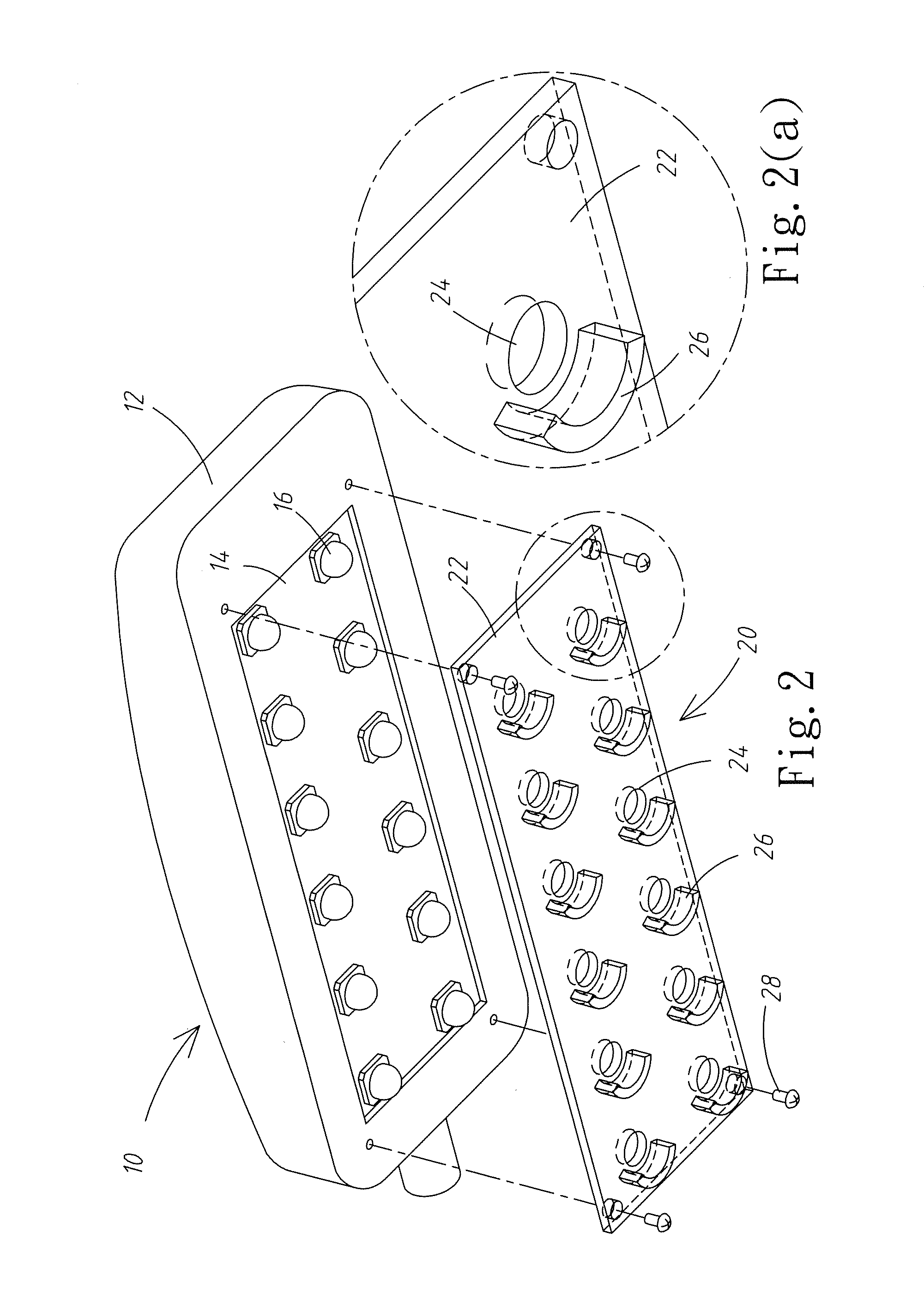
The present invention provides a light shielding plate for outdoor LED lighting devices. The plate has a protrusion block that reflects and redistributes lights emitted by LEDs or LEDs plus a secondary lens set, to achieve the effect of shielding lights. The reflecting surface of the protrusion block has curved surfaces of various designs to fully utilize the shielded light and achieve power saving. The design of the light shielding plate matches that of the outdoor LED lighting device, so its appearance does not seem odd.

Problems solved by technology

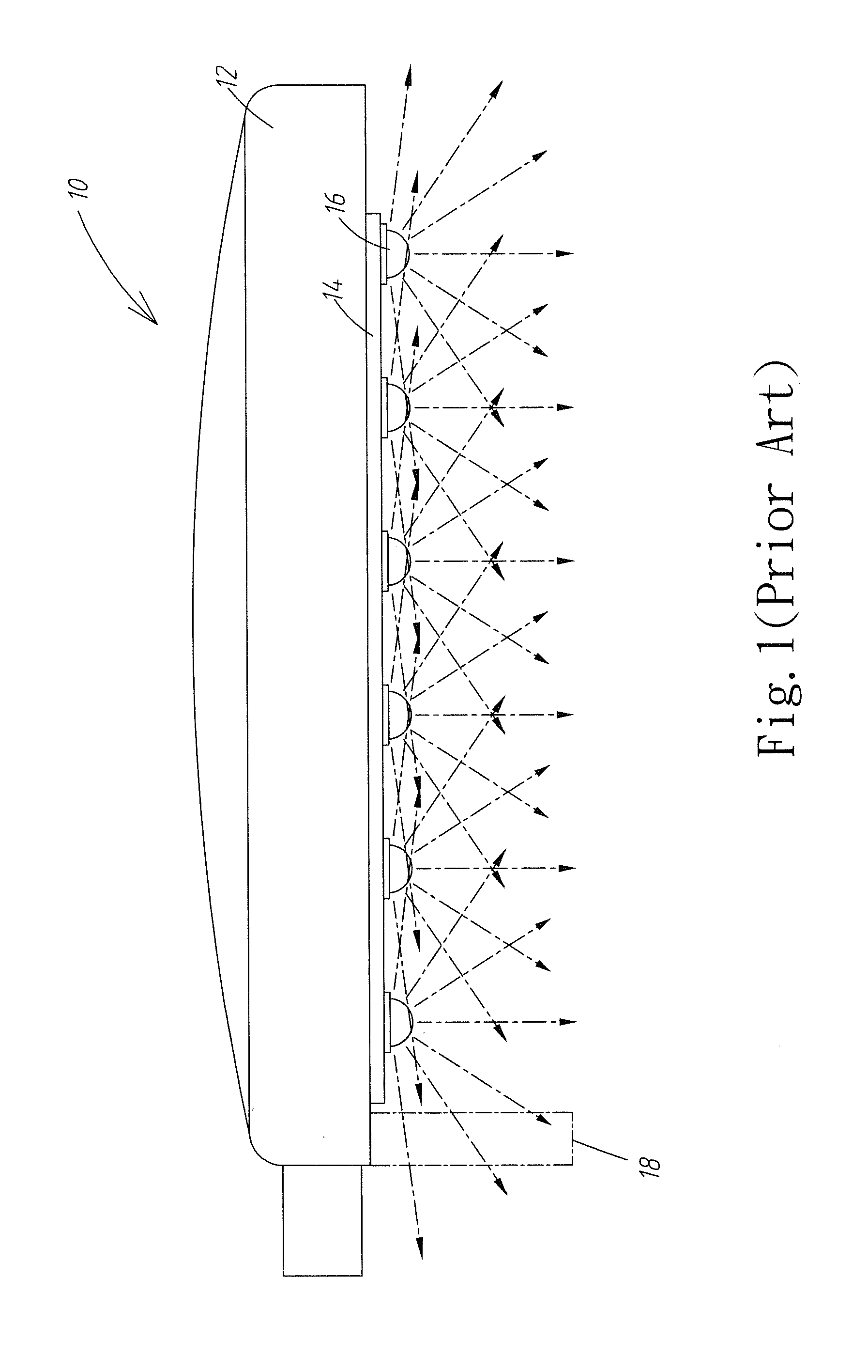
In such a case, when this kind of LED lighting device is placed in residential area, it could lead to light trespass to the residents in this area, to become a problem or serious threat to the residents inside.
Since the lights of LED street light getting into the room of the house could interfere with the normal routine of daily life, such as sleeping of the residents, or even seriously affect the generation of hormone in human body, hereby leading to the danger of incurring cancer.
However, for this approach of light shielding, not only its outer appearance seems rather odd, but it could also adversely affect the safety of the maintenance staff repairing or replacing the LED street lights.
In addition, it could harm the birds flying around, also, the blocked light can not be used effectively, thus leading to waste of electricity.
Therefore, presently, the design and performance of light shielding plate for outdoor LED lighting device of the prior art is not quite satisfactory, and it has much room for improvement.

Method used


Image

  • Light shielding plate of outdoor LED lighting device
  • Light shielding plate of outdoor LED lighting device
  • Light shielding plate of outdoor LED lighting device

Examples


Embodiment Construction

[0024]The purposes, constructions, features, functions and advantages of the present invention can be appreciated and understood more thoroughly through the following detailed descriptions with reference to the attached drawings. And, in the following, various embodiments are described in explaining the technical characteristics of the present invention.

[0025]The present invention discloses a light shielding plate disposed on an outdoor LED lighting device, comprising: a main body, disposed on a light exit plane of an outdoor LED lighting device, and at least a protrusion block is provided on the main body, to shield, reflect, and distribute light emitted from LEDs or LEDs plus a secondary lens set of the outdoor LED lighting device, The outdoor LED lighting device referred to herein can be a street light, a park light, a landscape viewing light, or a wall washing light, etc.

[0026]The present invention makes use of the unique light emitting way and pointing characteristic of LEDs, a...


PUM


Abstract

A light shielding plate of an outdoor LED lighting device, comprising a main body disposed on a light exit plane of said outdoor LED lighting device. On a bottom surface of said main body is provided with at least a protrusion block, to reflect lights coming from LEDs or said LEDs plus a secondary lens set of said outdoor LED lighting device, in achieving light shielding effect. Moreover, on a reflection plane of said protrusion block is further provided with curved planes of various designs, to fully utilize the shielded light, so that lights are redistributed in areas of effective illumination, in further realizing power saving requirements.

Description

BACKGROUND OF THE INVENTION[0001]1. Field of the Invention[0002]The present invention relates to a light shielding plate, and in particular to a light shielding plate of an outdoor LED lighting device.[0003]2. The Prior Arts[0004]Nowadays, in order to provide sufficient illumination outdoors at night, lighting device is an important and indispensable tool, to protect the safety of people walking outdoors and car drivers. By way of examples, in order to protect the safety of pedestrians and car drivers at night, lighting devices are put on both sides of the roads in general, and that constitutes an essential part of Basic Public Utility. For this reason, light-emitting-diode (LED) has become a mainstay of lighting for now and future, since it can achieve both energy conservation and environment protection, due to its advantages of long service life, low power consumption, fast response speed, high efficiency, and energy conservation.[0005]Refer to FIG. 1, for a schematic diagram of a...

Claims


Application Information

Patent Timeline
IPC IPC(8): F21V5/00F21S4/00
CPCF21S8/033F21S8/08F21V7/00F21Y2105/001F21W2131/10F21W2131/103F21Y2101/02F21V11/00F21Y2105/10F21Y2115/10F21V7/0083
Inventor CHEN, CHUNG-JUNGCHEN, YU-SHENGCHANG, KUO-HUI
Owner EXCELLENCE OPTO INC
Learn More