Mandibular manipulator and related methods

Inactive Publication Date: 2013-01-24
KOSMO TECH
View PDF15 Cites 26 Cited by
  • Summary
  • Abstract
  • Description
  • Claims
  • Application Information

AI Technical Summary

Benefits of technology

The invention is a device that allows for precise measurement and positioning of the mandible relative to the maxilla for dental applications such as the use of an acoustic oral pharyngometer instrument to measure the area and volume of the throat opening of a patient as they breathe. The device has two mechanical connections that allow for motion in both an anterior / posterior direction and a vertical direction, as well as a third connection that allows for sagittal or right and left relative motion. Gradated scales or indicators are marked on the connecting frame of the instrument to accurately quantify the movement in all three directions. The position of the mandible can be measured or positioned while using electrodiagnostic equipment or radiology. The device allows for real-time adjustment without the need for sequential removal of the adjusting instrument. This invention pairs with a dental appliance to hold the mandible in a set position as the patient sleeps to prevent breathing difficulties.

Problems solved by technology

Several problems can occur with the current method of achieving desired mandibular position because the patient is instructed to, e.g., position their mandible as the dental / medical procedure is performed.
Present methods lack the precision and repeatability needed to analyze a patient in real time with any diagnostic instrument or during other dental procedures requiring mandibular manipulation.
This trial-and-error method not only increases the diagnosis time, but prevents an accurate means of noting where the relative position of the mandible lies in relation to the maxilla.
And, in some cases, the patient becomes dissatisfied with the overall lack of good results and gives up.

Method used


Image

  • Mandibular manipulator and related methods
  • Mandibular manipulator and related methods
  • Mandibular manipulator and related methods

Examples


Embodiment Construction

[0052]The following terminology is used herein:

[0053]Dental Articulator: Mechanical instruments that simulate the temporomandibular joints and jaws to which maxillary and mandibular casts are attached. The entire assembly attempts to reproduce the movements of the mandible and the various tooth-to-tooth relationships that accompany those movements.

[0054]Maxilla: anatomy: of a pair of bones of the human skull fusing in the mid line and forming the upper jaw.

[0055]Dental: The irregularly shaped bone forming half of the upper jaw. The upper jaw is made up of the two maxillae.

[0056]Incisal edges of the lower to upper central incisor teeth.

[0057]Anteroposterior: Anatomical term referring to an axis and for the purpose of this application defines an axis from front to back of the mouth.

[0058]Sagittal: A vertical plane passing through the standing body from front to back.

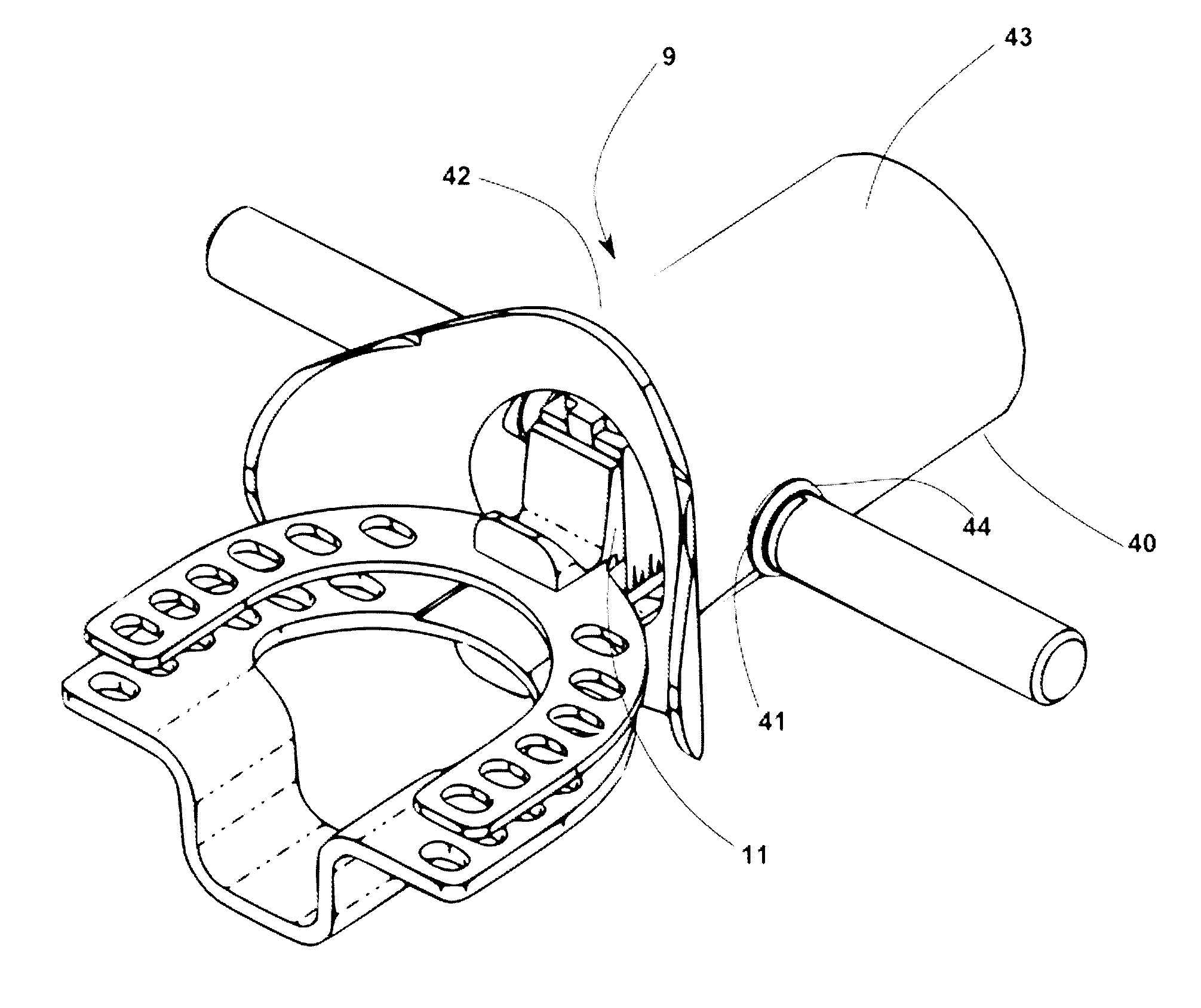
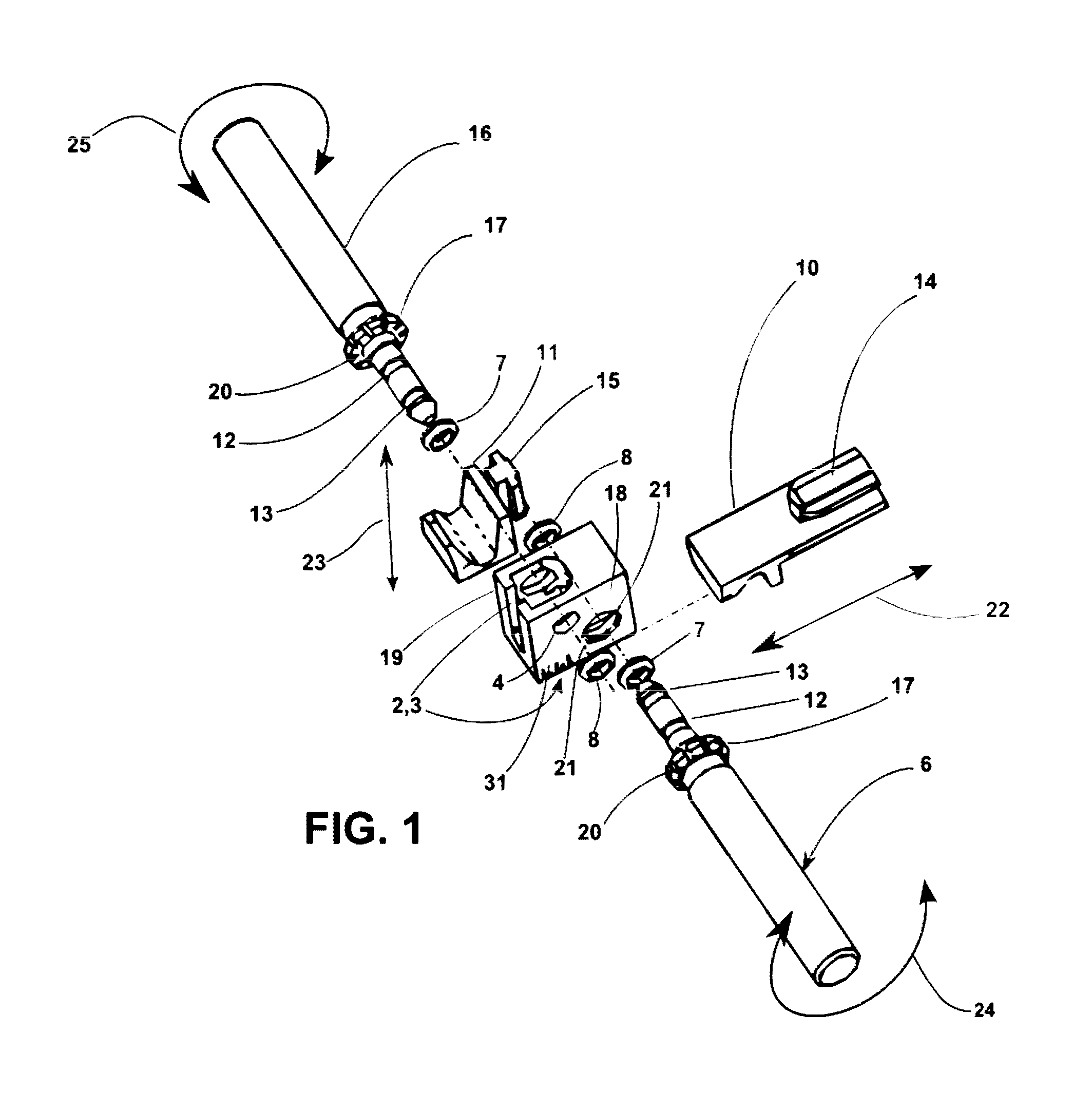
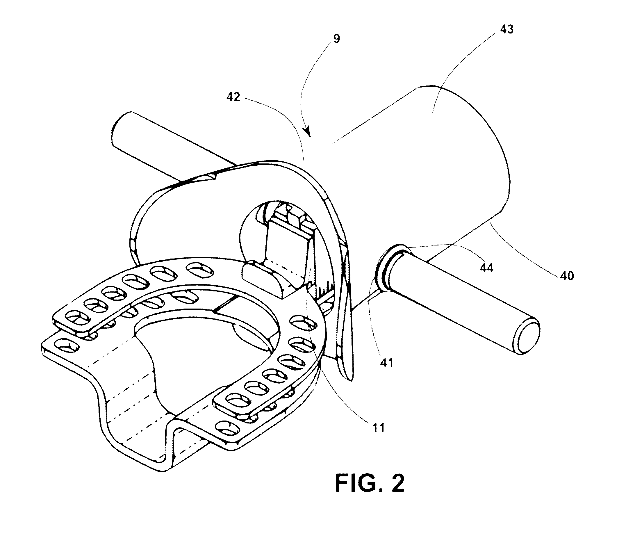
[0059]With reference now to FIGS. 1, 2, and 3, arrow 9 shows the overall mandibular manipulator as a self-contained unit...


PUM

PropertyMeasurementUnit
Electrical resistanceaaaaaaaaaa

Abstract

Described is a mandibular manipulator instrument as a standalone tool or with associated mouthpiece that includes two interlocking laterally sliding frames comprising a movable upper and a lower incisor pull, shaped for receiving a patient's central incisor teeth and a pair of pinion shafts for driving the upper and lower incisor pulls. A screw thread is used to provide a precise lateral motion for the sagittal measurement. The mouthpiece is constructed of resilient rubber. The manipulator is positioned and held in the resilient rubber mouthpiece by means of the two pinions protruding through acoustically tight apertures respective to each pinion's position. The manipulator can be used for other applications in an embodiment without the mouthpiece and / or in combination with a bite registration shape that is part of the manipulator frame.

Description

CROSS-REFERENCE TO RELATED APPLICATIONS[0001]This application is a continuation-in-part of co-pending U.S. patent application Ser. No. 13 / 130,517, filed May 20, 2011, U.S. Pat. No. 8,226,407 (Jul. 24, 2012), which application is a national phase entry under 35 U.S.C. §371 of International Patent Application PCT / US2010 / 001839, filed Jun. 24, 2010, published in English as International Patent Publication WO 2011 / 005299 on Jan. 13, 2011, which claims the benefit under Article 8 of the Patent Cooperation Treaty and under 35 U.S.C. §119(e) to U.S. Patent Application Ser. No. 61 / 269,344, filed on Jun. 24, 2009, the disclosure of each of which is hereby incorporated herein in its entirety by this reference. This application is also a continuation of International Patent Application PCT / US2012 / 022089, filed Jan. 20, 2012, which claims the benefit under Article 8 of the Patent Cooperation Treaty and under 35 U.S.C. §119(e) to U.S. Patent Application Ser. No. 61 / 461,657, filed Jan. 21, 2011, ...

Claims


Application Information

Patent Timeline
IPC IPC(8): A61B5/11B23P11/00
CPCY10T29/49826A61B5/1121A61B5/4552A61B5/1076
Inventor HANEWINKEL, WILLIAM H.GLEESON, MICHAEL B.
Owner KOSMO TECH
Why Eureka
Try Eureka