Supercharge Your Innovation With Domain-Expert AI Agents!

Control computer system, method for controlling a control computer system, and use of a control computer system

Active Publication Date: 2013-01-24
CONTINENTAL TEVES AG & CO OHG
View PDF7 Cites 42 Cited by
  • Summary
  • Abstract
  • Description
  • Claims
  • Application Information

AI Technical Summary

Benefits of technology

The present invention aims to provide a control computer system that can tolerate errors and also be efficient simultaneously.

Problems solved by technology

Both permanent errors, which are caused, for example, by a defect introduced during production, and transient errors, which are caused, for example, by temporary electromagnetic interference, may occur in this case.
However, providing error tolerance, according to which the computer system thus continues to execute the desired program if an error occurs, is a particular challenge for processors with double redundancy.
After a parity error has been detected on one side, the associated processor is disconnected, with the result that it no longer has any influence on the system.
This procedure which is based on parity checking does not provide sufficient coverage of cases in which the availability of a redundant system is very desirable even after the occurrence of a lockstep error.
The parity check can lead, for example, to an incorrect decision if the two internal redundant units simultaneously show different multi-bit errors.
The classic minimum configuration for an error-tolerant system, which comprises triple redundancy (TMR: Triple modular redundancy) of processors and a jointly used memory, is still an expensive solution for many safety architectures whose safety concept is based on the use of two redundant processors running in lockstep or synchronously.
However, error tolerance is a particular challenge for processors with double redundancy.
However, this method is too expensive for many embedded systems since one processor pair is not used when there are no errors and the described method thus provides a poor cost / performance ratio.
Since each computation module synchronously processes the same instruction string, this computer system is not very efficient.
Systems and methods in accordance with the previously mentioned documents have the disadvantage that a high degree of redundancy must be made available since, when there are no errors, at least one processor pair is inactive or executes the same program as the active processor pair which drives peripheral units.
Therefore, each individual processor must provide the entire computation power required, as a result of which the known computer systems do not operate in a very efficient manner.
This is undesirable from the point of view of costs, in particular in the case of systems produced in large quantities.
The method described in U.S. Pat. No. 7,366,948 B2 is a very expensive solution for embedded systems.
There is also the fact that other components, apart from the processor cores, cannot always be implemented in a redundant manner.
Conventional methods do not consider this boundary condition of non-redundant components in the approach to ensuring availability in safety architectures based on redundant processors.
Another problem as regards ensuring the availability of processors in safety architectures is that a processor which has previously failed can be started up again only after a safety check has been successfully concluded.

Method used


Image

  • Control computer system, method for controlling a control computer system, and use of a control computer system
  • Control computer system, method for controlling a control computer system, and use of a control computer system
  • Control computer system, method for controlling a control computer system, and use of a control computer system

Examples


Embodiment Construction

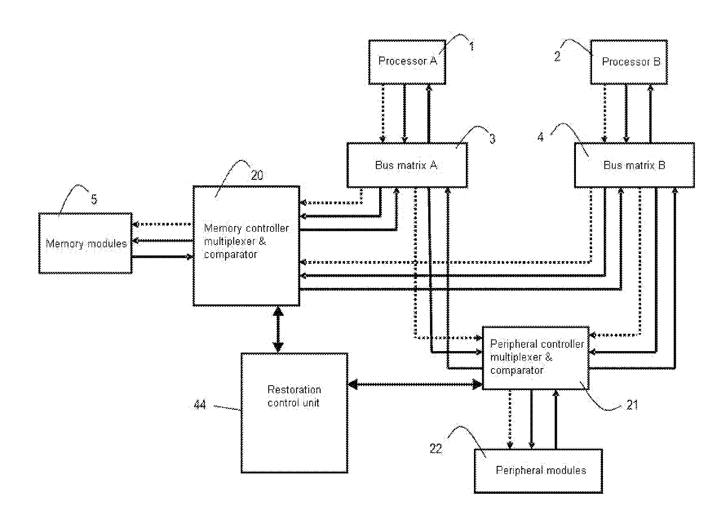
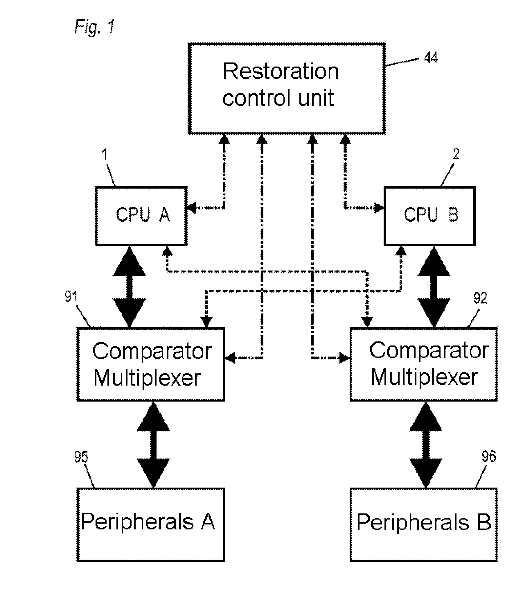
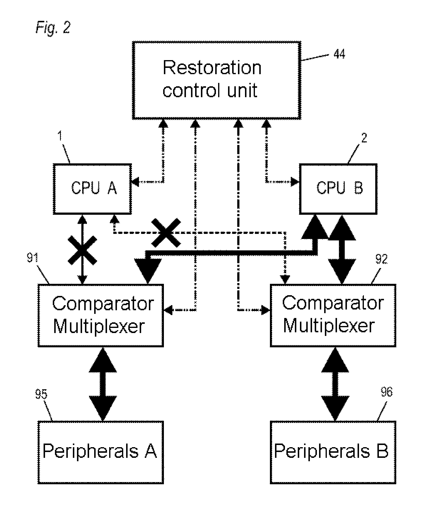
[0082]FIG. 1 schematically shows a control computer system or a control apparatus having a first processor 1 (shown as CPU A) and a second processor 2 (shown as CPU B) and a first multiplexer 91 and a second multiplexer 92. Each of the multiplexers 91, 92 forms a unit with a respective comparison device which is designated a comparator / multiplexer in the figures (and referred to in this manner in this description). Each of the multiplexers 91, 92 is connected to a respective peripheral unit 95, 96 and makes it possible for the processors 1, 2 to optionally access the peripheral units 95, 96. A restoration control unit 44 is connected both to the two processors 1, 2 and to the multiplexers 95, 96.

[0083]The processors 1, 2 may also be processor cores.

[0084]The bold arrows illustrated in FIG. 1 show the data flow actually conveyed by the multiplexers 91, 92 from the processors 1, 2 to the peripheral units 95, 96. Processor 1 communicates with peripheral unit 95 and controls the latter,...


PUM


Abstract

A control computer system comprising at least two modules (1, 2, 1001, 1002, 1003, 1004, 1021, 1071) which are designed to be redundant with respect to one another. The control computer system having at least one comparison unit (20, 21, 91, 92, 1011, 1012) for monitoring the synchronization state of the at least two redundant modules (1, 2, 1001, 1002, 1003, 1004, 1021, 1071) and for detecting a synchronization error at least one peripheral unit (95, 96, 1022, 1030, 1031, . . . , 1038). At least one switching matrix (21, 1013, 1063) which is set up to allow or block access to the at least two redundant modules or access to the peripheral unit (95, 96, 1022, 1030, 1031, . . . , 1038) by the at least two redundant modules, and an error-handling unit (44, 1080) which is set up to receive signals from the at least one comparison unit (20, 21, 91, 92, 1011, 1012) and to drive the at least one switching matrix (1013, 1063) in order to completely or selectively prevent access to the at least two redundant modules or access to the peripheral unit by the at least two redundant modules.

Description

CROSS-REFERENCE TO RELATED APPLICATIONS[0001]This application claims priority to German Patent Application Numbers 1020 1000161.5, filed Mar. 23, 2010, 1020100041890.0, filed Oct. 1, 2010, and PCT / EP2011 / 054144, filed Mar. 18, 2011.FIELD OF THE INVENTION[0002]The following invention relates to a redundant electronic processor controller and to a control method, in particular to a redundant two-processor controller and a multicore redundant control computer system.BACKGROUND OF THE INVENTION[0003]It is known practice to have two processors execute the same instructions in a lockstep mode and to determine whether an error has occurred by comparing the output data. In this case, the two processors may be operated in clock synchronism or with a certain temporal offset (which is accordingly compensated for during comparison). Both permanent errors, which are caused, for example, by a defect introduced during production, and transient errors, which are caused, for example, by temporary el...

Claims


Application Information

Patent Timeline
IPC IPC(8): G06F11/07
CPCG06F11/1641G06F11/165G06F11/1645G06F11/2035G06F11/2043G06F11/203G06F11/184
Inventor KABULEPA, LUKUSA DIDIEREHRENBERG, THORSTENBAUMEISTER, DANIEL
Owner CONTINENTAL TEVES AG & CO OHG
Features
  • R&D
  • Intellectual Property
  • Life Sciences
  • Materials
  • Tech Scout
  • Unparalleled Data Quality
  • Higher Quality Content
  • 60% Fewer Hallucinations
Learn More