Catcher's leg guard

a leg guard and catcher technology, applied in the field of leg guards, can solve problems such as discomfort for catcher's legs

Inactive Publication Date: 2013-01-31
MINSON ENTERPRISES
View PDF3 Cites 15 Cited by
  • Summary
  • Abstract
  • Description
  • Claims
  • Application Information

AI Technical Summary

Benefits of technology

[0008]The main object of the present invention is to provide a catcher's leg guard having an upper knee c

Problems solved by technology

However, such one-piece hard knee cover 60 cannot bend in accordance w

Method used


Image

  • Catcher's leg guard
  • Catcher's leg guard
  • Catcher's leg guard

Examples


Embodiment Construction

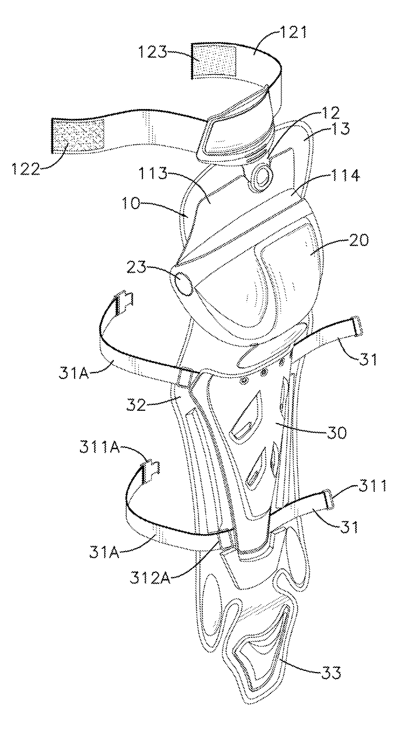
[0015]With reference to FIG. 1, a catcher's leg guard in accordance with the present invention comprises an upper knee cover 10, a lower knee cover 20 and a shin cover 30.

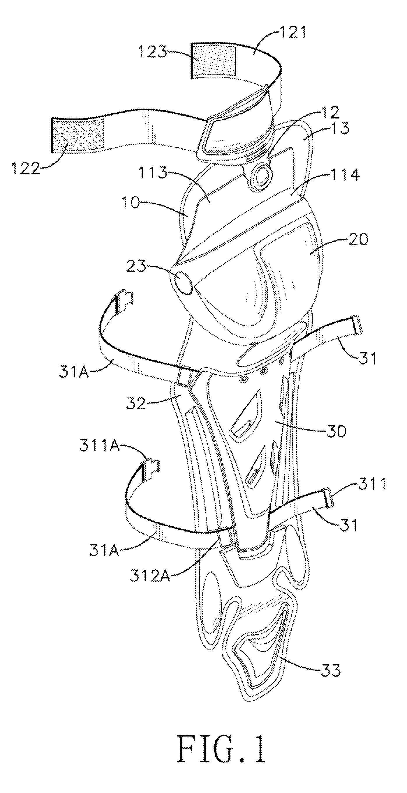
[0016]With further reference to FIG. 2, the upper knee cover 10 includes an inner surface, a curved shell 11, a connecting sheet 12 and a kneepad 13. The shell 11 has a curved outer surface, two sides, a top edge, two pivoting holes 111, two guiding blocks. 112, a connecting portion 113 and a barrier protrusion 114. The pivoting holes 111 are respectively formed through the sides of the shell 11. The guiding blocks 112 respectively protrude from the sides of the shell 11 and are respectively adjacent to the pivoting holes 111. The connecting portion 113 extends from the top edge of the shell 11. The barrier protrusion 114 is formed on and protrudes from a bottom edge of the connecting portion 113. The connecting sheet 12 is connected pivotally to the connecting portion 113 of the shell 11, is positioned above the c...


PUM


Abstract

A catcher's leg guard includes an upper knee cover, a lower knee cover and a shin cover. The upper knee cover has a kneepad attached securely to an inner surface of the upper knee cover. The lower knee cover is connected rotatably to the upper knee cover. The shin cover is mounted below the lower knee cover and has an inner surface and a shin pad. The shin pad is attached securely to the inner surface of the shin cover. When a catcher is in a standing position, the upper knee cover retracts relative to the lower knee cover. When the catcher is in a squatting position, the upper knee cover and the lower knee cover are open to fully cover a knee of the catcher. Therefore, the leg guard can be securely and comfortably worn on the catcher's leg.

Description

BACKGROUND OF THE INVENTION[0001]1. Field of the Invention[0002]The present invention relates to a leg guard, and more particularly to a leg guard that can be worn on a catcher's leg securely.[0003]2. Description of the Prior Arts[0004]Leg guards worn in front of legs are protective equipment commonly used by catchers in baseball or softball and serve to protect the legs from impact by a ball at high speed.[0005]With reference to FIG. 5, a conventional catcher's leg guard generally comprises a knee cover 60, a shin cover 70 and multiple straps 80. The knee cover 60 includes an inner surface and a kneepad 61. The kneepad 61 is attached to the inner surface of the knee cover 60 and extends downward to connect to the shin cover 70. The shin cover 70 includes a shin pad 71 attached to an inner surface of the shin cover 70. The straps 80 are respectively mounted on two sides of the kneepad 61 and the shin cover 70. In use, the straps 80 are fastened around a shank 91 and a thigh 92 to ma...

Claims


Application Information

Patent Timeline
IPC IPC(8): A41D13/06
CPCA63B71/1225A63B2209/10A41D13/065A41D13/0543A63B2243/0004A63B2102/18A63B2102/182
Inventor CHEN, TAI-HENG
Owner MINSON ENTERPRISES
Why Eureka
Try Eureka