
Blowout preventer head removal tools and methods

Active Publication Date: 2013-01-31
TRIPLE C RIG WELDING
View PDF4 Cites 0 Cited by
  • Summary
  • Abstract
  • Description
  • Claims
  • Application Information

AI Technical Summary

Benefits of technology

The patent describes a tool for removing a threaded, blowout-preventer head from a blowout preventer using a rotating device. The tool includes a longitudinal shaft, a lifting eye member, and a head-mounting member. The shaft has a first end and a second end. The lifting eye member is attached to the first end of the shaft. The head-mounting member is attached to the second end of the shaft. The tool has a combined longitudinal length that allows a rotating device to be coupled to a portion of the shaft and remove the blowout-preventer head. The head-mounting member includes a mounting plate, gussets, torque arms, and an anchor bar. The tool is designed to safely and efficiently remove the blowout-preventer head without causing damage or injury.

Problems solved by technology

In the early years of oil production it was not uncommon for a blowout on an oil well being drilled to occur.
Blowouts are both dangerous and wasteful.
Blowouts would often push the drill string out of the well and injure or kill workers.
At times, however, the fluid density was not adequate and a blowout would still occur.
The process is more dangerous, difficult, and time consuming than desired.

Method used


Image

  • Blowout preventer head removal tools and methods
  • Blowout preventer head removal tools and methods
  • Blowout preventer head removal tools and methods

Examples


Embodiment Construction

[0018]In the following detailed description of the preferred embodiments, reference is made to the accompanying drawings that form a part hereof, and in which is shown, by way of illustration, specific embodiments in which the invention may be practiced. These embodiments are described in sufficient detail to enable those skilled in the art to practice the invention, and it is understood that other embodiments may be utilized and that logical structural, mechanical, electrical, and chemical changes may be made without departing from the spirit or scope of the invention. To avoid detail not necessary to enable those skilled in the art to practice the invention, the description may omit certain information known to those skilled in the art. The following detailed description is, therefore, not to be taken in a limiting sense, and the scope of the present invention is defined only by the appended claims.

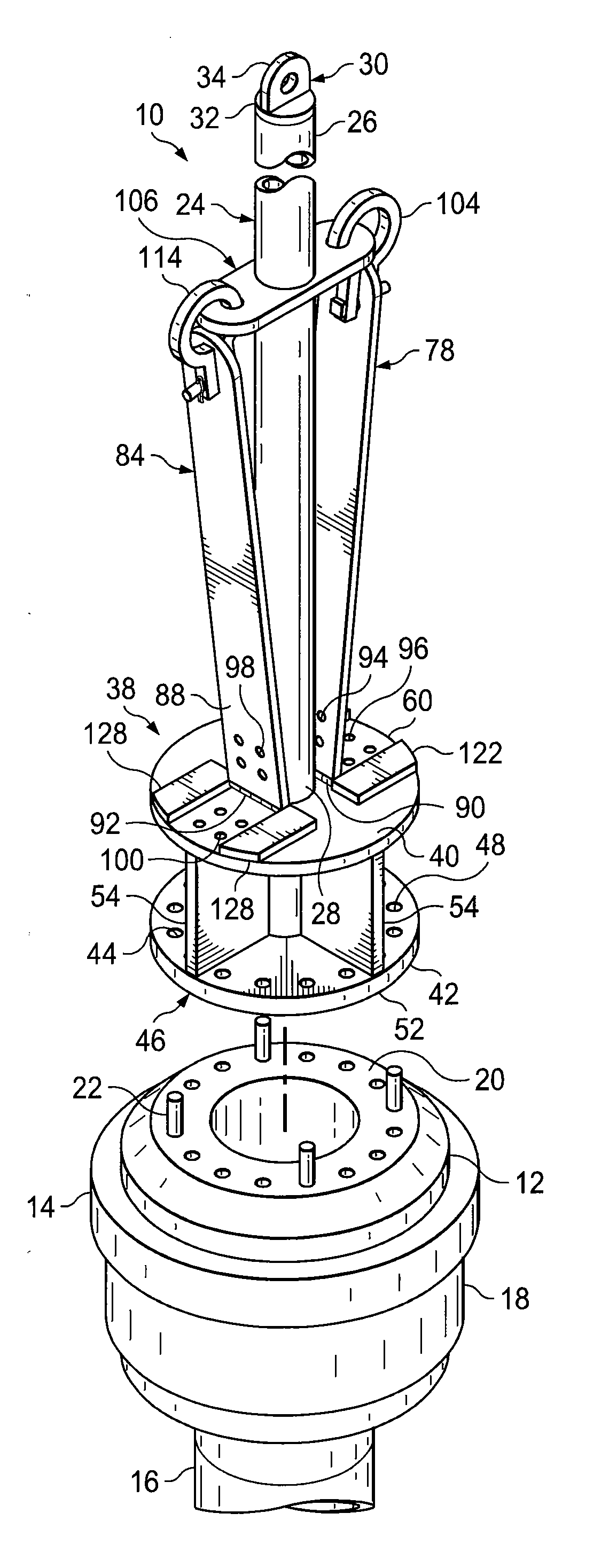
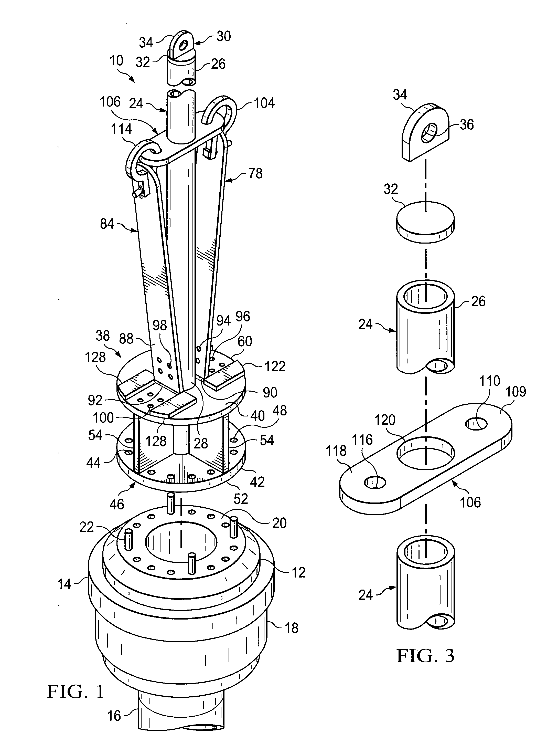
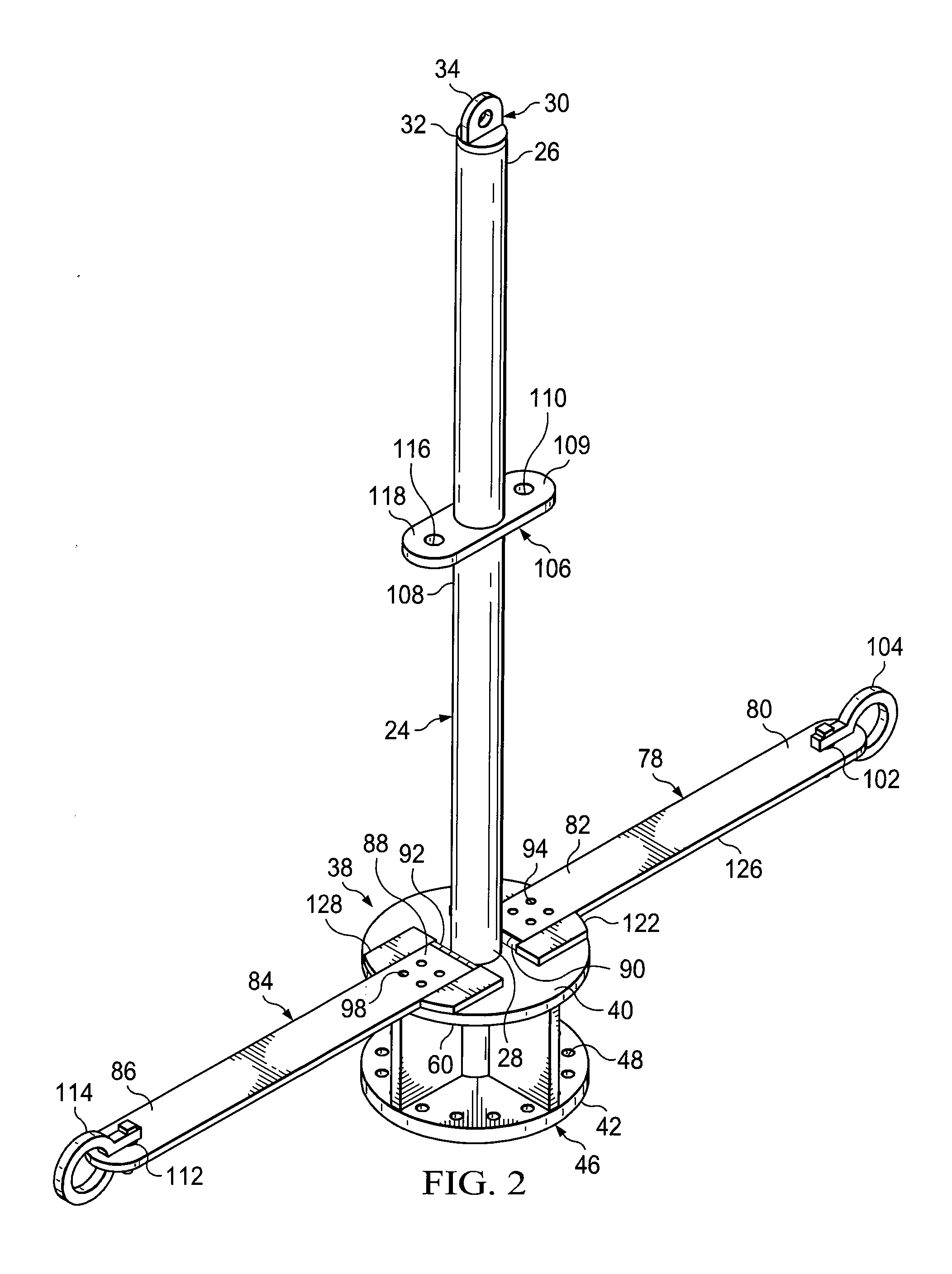
[0019]Referring now to the drawings and initially to FIG. 1, an illustrative embodi...


PUM

PropertyMeasurementUnit
Lengthaaaaaaaaaa
Lengthaaaaaaaaaa
Lengthaaaaaaaaaa

Abstract

Specialized tools and methods are presented for use on blowout preventers on oil and gas rigs. The specialized tools releseably attach to a threaded, blowout-preventer head to remove the same. In one instance, the tool has a longitudinal shaft, a lifting eye member at one end and a head-mounting member at the other. The head-mounting member attaches to the threaded, blowout-preventer head. In some instances, one or more torque arms may be included to add additional torque. Other embodiments and methods are also included.

Description

RELATED APPLICATION[0001]The present application claims the benefit, under 35 U.S.C. §119(e), of the filing of U.S. Provisional Patent Application Ser. No. 61 / 511,832, entitled “Annular Seal Removing Tool Using Top Drive or Kelly,” filed Jul. 26, 2011, and which incorporated herein by reference for all purposes.FIELD[0002]The disclosure herein relates to blowout preventers for use on oil rigs, and more particularly, but not by way of limitation, to blowout preventer head removal tools and methods.BACKGROUND[0003]In the early years of oil production it was not uncommon for a blowout on an oil well being drilled to occur. A blowout is an uncontrolled release of oil from an oil well or gas from a gas well. One may think of the classic picture of a gusher at Spindletop, Tex. throwing oil out of the top. Blowouts are both dangerous and wasteful. Blowouts would often push the drill string out of the well and injure or kill workers.[0004]With the advent of rotary drilling techniques, which...

Claims


Application Information

Patent Timeline
IPC IPC(8): B23P19/00B23P17/04
CPCE21B19/00E21B33/064Y10T29/49815Y10T29/49826Y10T29/53E21B19/16Y10T29/53843
Inventor CRANFORD, KATHYLEENCRANFORD, BOBBY DALE
Owner TRIPLE C RIG WELDING
Features
  • Generate Ideas
  • Intellectual Property
  • Life Sciences
  • Materials
  • Tech Scout
  • Unparalleled Data Quality
  • Higher Quality Content
  • 60% Fewer Hallucinations
Learn More