
Polymer light emitting element
- Summary
- Abstract
- Description
- Claims
- Application Information
AI Technical Summary
Benefits of technology
Problems solved by technology
Method used
Image

Examples
example 1
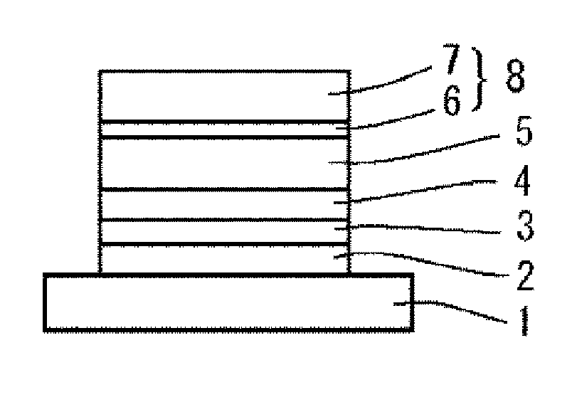
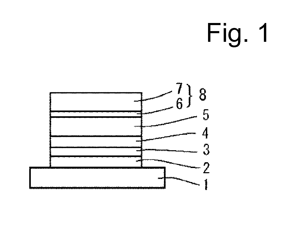
[0151]FIG. 1 is a schematic sectional view showing a structure of an organic EL device, which is one embodiment of the present invention.
[0152](1-1: Formation of Hole Injection Layer) A composition for forming a hole injection layer was applied onto a glass substrate 1 provided with an ITO anode 2 thereon by a spin coating method to obtain a coating film with a film thickness of 60 nm.
[0153]The substrate provided with the coating film was heated at 200° C. for 10 minutes to make the coating film insoluble, and then the substrate was naturally cooled to room temperature to obtain a hole injection layer 3. Here, a PEDOT:PSS aqueous solution (poly(3,4-ethylenedioxythiophene)-polystyrenesulfonic acid, product name “Baytron”), which is available from H.C. Starck-V TECH Ltd., was used for the composition for forming a hole injection layer.
[0154](1-2: Formation of Hole Transporting Layer)
[0155]The polymer hole transporting compound and xylene were mixed in such a way that percentage of the...
example 2
[0167]A polymer light-emitting device 2 was prepared in the same manner as in Example 1 except that the mixing molar ratio of NaF and Mg was set at NaF:Mg=2:1 in the first electrode layer. The luminance level when driven at 4V, the maximum luminous efficiency and the luminance half-decay lifetime were measured. The results of measurement are shown in Table 1.
example 3
[0168]A polymer light-emitting device 3 was prepared in the same manner as in Example 1 except that the mixing molar ratio of NaF and Mg was set at NaF:Mg=4:6 in the first electrode layer. The luminance level when driven at 4V, the maximum luminous efficiency and the luminance half-decay lifetime were measured. The results of measurement are shown in Table 1.
PUM
| Property | Measurement | Unit |
|---|---|---|
| Fraction | aaaaa | aaaaa |
Abstract
Description
Claims
Application Information