
Transport housing for a coil or a coil block

a technology for transporting housings and coils, which is applied in the direction of packaging, other accessories, transformers/react mounting/support/suspension, etc., can solve the problems of time and capacity, technical equipment cannot be provided at a reasonable expense, and equipment cannot meet the needs of the customer

Active Publication Date: 2013-02-14
ABB POWER GRIDS SWITZERLAND AG
View PDF11 Cites 7 Cited by
  • Summary
  • Abstract
  • Description
  • Claims
  • Application Information

AI Technical Summary

Benefits of technology

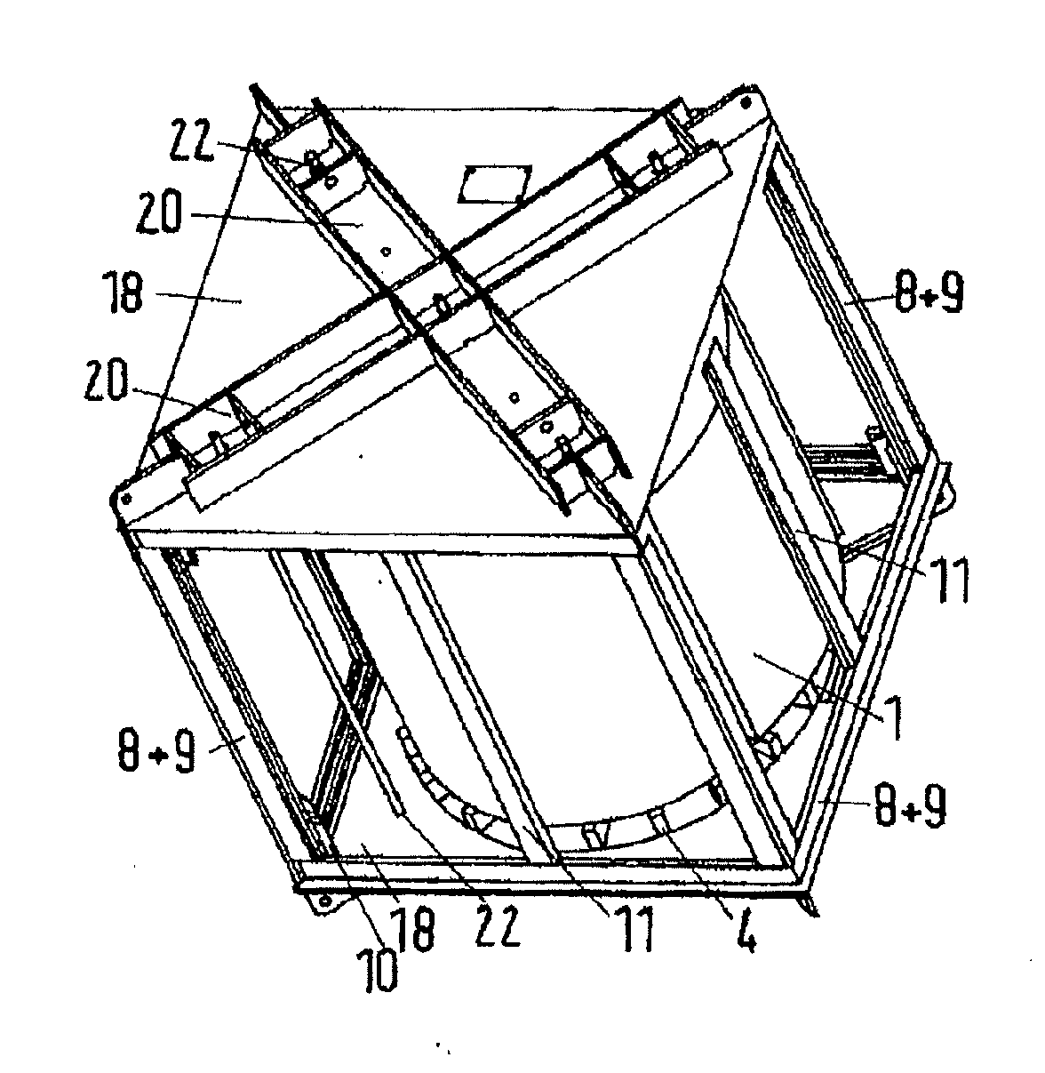
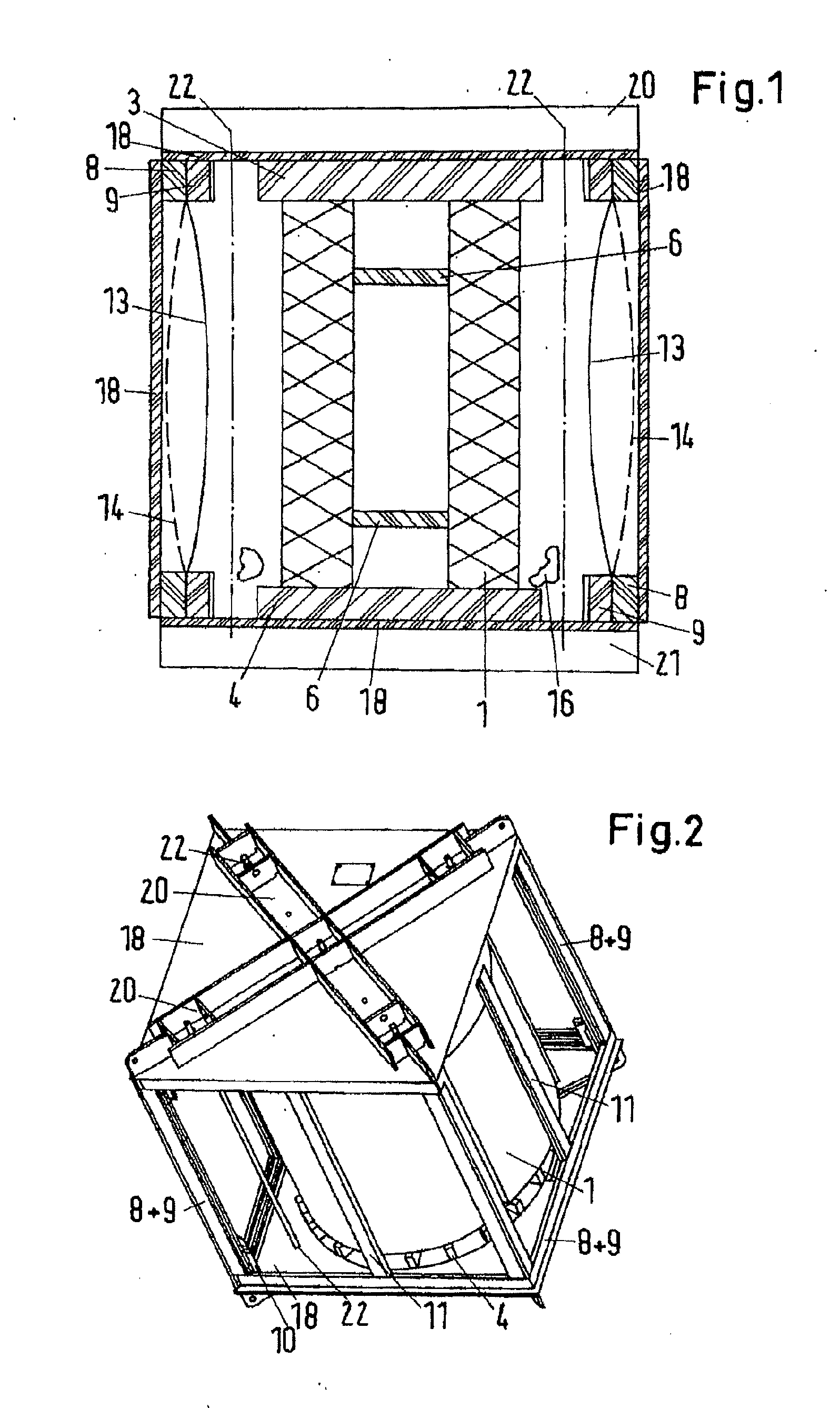
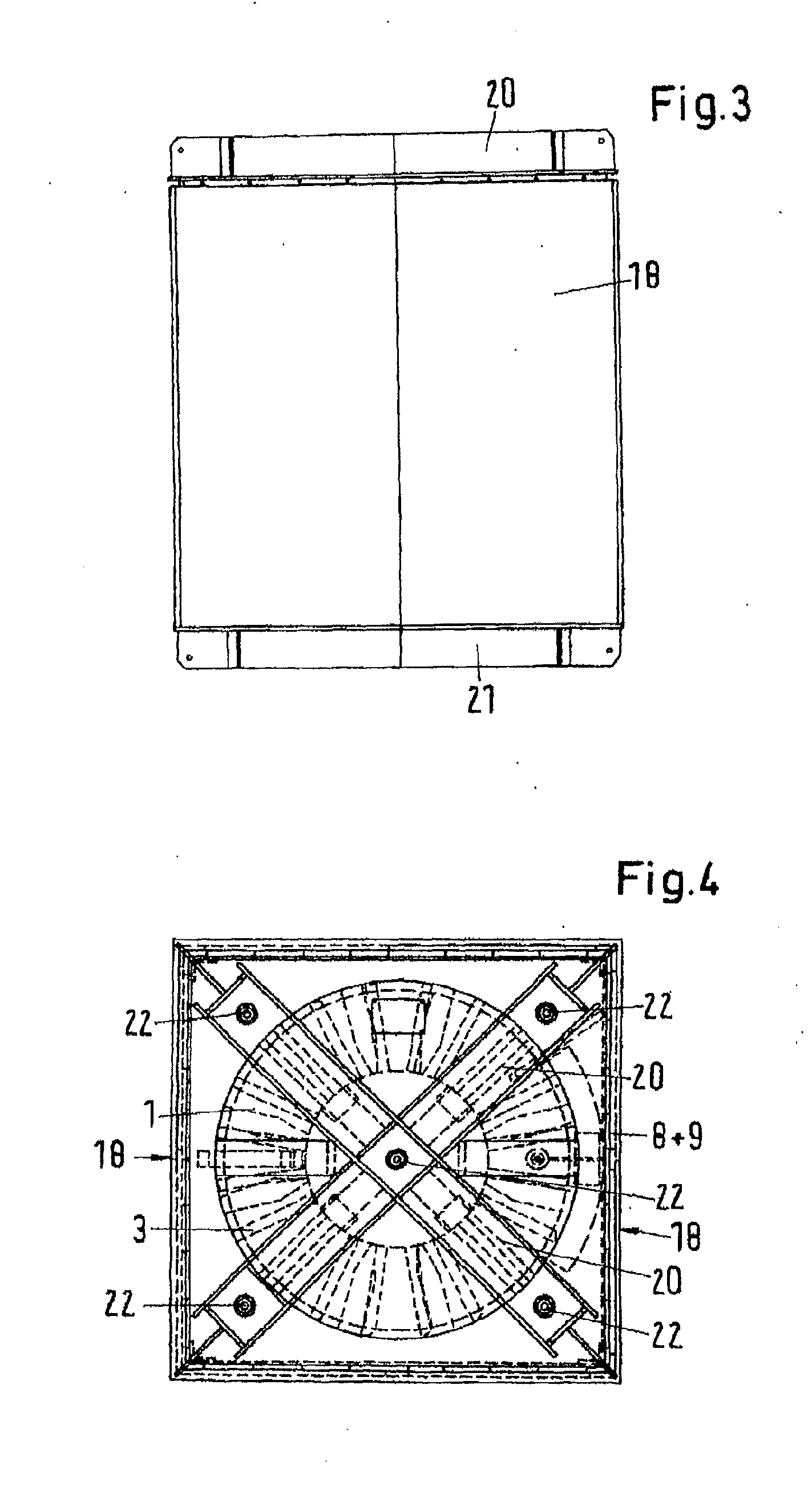
The patent is about a transport housing for a coil or coil block. It includes an upper and lower pressing plate to hold the coil or coil block in place using tie rods. The housing also has a frame with a movable membrane that can be raised and lowered, as well as an outer housing to protect the membrane and allow it to move. Its purpose is to provide a secure and safe way to transport and protect the coil or coil block.

Problems solved by technology

The specification according to (A) results from on-site repairs, where technical equipment for drying the coils is not usually available and the technical equipment cannot be provided at a reasonable expense.
When coils are transferred between different manufacturing locations without dry transportation, the coils are first dried before installation, which often results in time and capacity problems.
However, the technical prerequisites for pressing coils and coil blocks are not usually available on site.
For example, when coils are transferred between different manufacturing locations, the same time and capacity problems can occur as with drying.
In addition it is not technically possible to transport coils without any axial clamping.
Their construction with correspondingly thin supporting cylinders is not designed for unsupported transportation.
Thus, it is not possible to transport coils without radial fixing or support.
According to known transport housings, the specifications according to (A) is usually fulfilled by transporting the coils in pressure-tight transport tanks, which are specially designed for this means of transport and are therefore expensive.
The previous implementation of the processes according to (A) for dry transportation by means of transport tanks due to their construction and their manufacture, uses pressure-tight transport tanks, which are very expensive, i.e. the price of a transport tank is up to 40% of the cost of the leg coils to be transported.

Method used


Image

  • Transport housing for a coil or a coil block
  • Transport housing for a coil or a coil block
  • Transport housing for a coil or a coil block

Examples


Embodiment Construction

[0025]The disclosure is based on providing a cost-effective transport housing for a coil or a coil block which fulfils the above-mentioned specifications.

[0026]According to the disclosure, a transport housing for a coil or a coil block includes an upper and lower pressing plate, wherein the coil or the coil block is arranged between the two pressing plates and the coil or coil block can be clamped against the upper and lower pressing plates with a plurality of tie rods in the manner of an axial clamping configuration. The axial clamping configuration having a frame, which encloses the coil or the coil block to which a membrane, movable both towards the interior of the transport housing and towards the outside, is fixed, and an outer housing which, provides mechanical protection for the membrane and, enables unhindered or allows movement of the membrane to the outside.

[0027]According to an exemplary embodiment, the coils or pre-assembled coil blocks withstand the loads of transportat...


PUM


Abstract

A transport housing for a coil or a coil block, having an upper and a lower pressing plate, wherein the coil or the coil block is arranged between the two pressing plates and the latter can be braced against each other by a plurality of tension rods in the manner of an axial tension configuration. A frame enclosing the coil or the coil block to which a membrane, movable both toward the inner chamber of the transport housing and toward the outside, is fastened and having an outer housing which provides mechanical protection for the membrane and enables unhindered or allows movement of the membrane to the outside.

Description

RELATED APPLICATION(S)[0001]This application claims priority as a continuation application under 35 U.S.C. §120 to PCT / EP2011 / 050610, which was filed as an International Application on Jan. 18, 2011 designating the U.S., and which claims priority to European Application 10001256.6 filed in Europe on Feb. 8, 2010. The entire contents of these applications are hereby incorporated by reference in their entireties.FIELD[0002]The disclosure relates to a housing for a coil or a coil block.BACKGROUND INFORMATION[0003]As result of the increasing number of on-site repairs to transformers, bottlenecks in coil manufacture in individual manufacturing locations of a transformer plant, and the simultaneously free winding capacity at other locations, the transportation of coils for oil-filled transformers less than 1000 kVA and pre-assembled coil blocks without the associated transformer tank and without associated cores is acquiring greater importance.[0004]Coils for oil-filled transformers are g...

Claims


Application Information

Patent Timeline
IPC IPC(8): B65D85/86
CPCB65D85/672B65D85/676H01F27/06H01F27/02H01F27/002
Inventor BRENDEL, HARTMUT
Owner ABB POWER GRIDS SWITZERLAND AG
Learn More