Self-adjusting seal

a self-adjusting and seal technology, applied in the direction of machines/engines, engine starters, liquid fuel engines, etc., can solve the problem of sealing tending to wear ou

Inactive Publication Date: 2013-02-14
GENERAL ELECTRIC CO
View PDF4 Cites 5 Cited by
  • Summary
  • Abstract
  • Description
  • Claims
  • Application Information

AI Technical Summary

Benefits of technology

[0003]A sealing system that self-adjusts according to atmospheric conditions is disclosed. The sealing system includes an annular seal casing mounted on a stationary component, the annular seal casing positioned such that a rotating component extends therethrough, at least one annular sealing agent configured to radially move with respect to the rotating component betwe

Problems solved by technology

In addition, known seals are contact seals, i.e., the seal is in constant contact with t

Method used


Image

  • Self-adjusting seal
  • Self-adjusting seal
  • Self-adjusting seal

Examples


Embodiment Construction

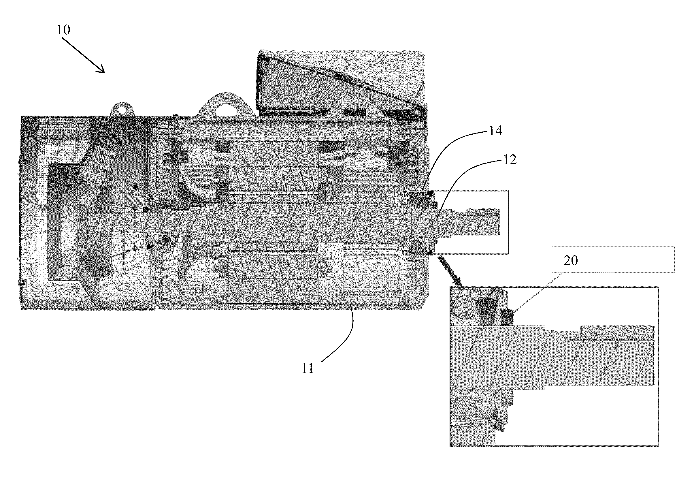
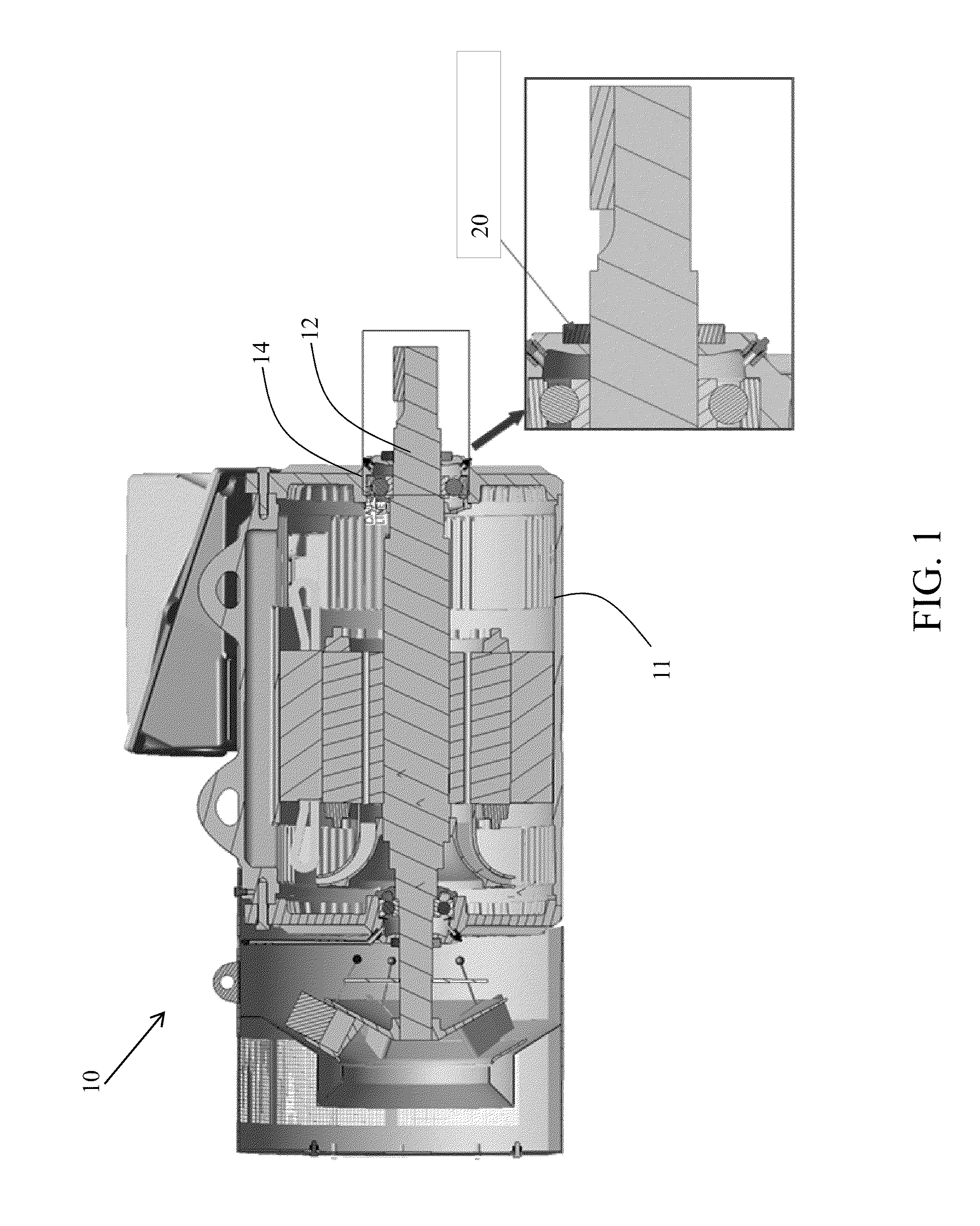
[0014]Turning to FIG. 1, a cross-sectional view of a motor 10, within a motor housing 11, is shown. Motor 10 includes a rotating component 12 (i.e., a rotor) partially within motor housing 11, and a stationary component 14. As known in the art, a seal 20 is included between stationary component 14 and rotating component 12. It is understood that while a motor is shown in FIG. 1, embodiments of the invention disclosed herein can be applied to a seal between any type of rotating component and stationary component.

[0015]As known in the art, seal 20 is an annular seal mounted on stationary component 14, with rotating component 12 extending through seal 20. Seal 20 acts to prevent contaminants in the atmosphere from migrating along rotating component 12 and entering motor housing 11. Seal 20 is referred to as a contact seal because it is in constant contact with rotating component 12.

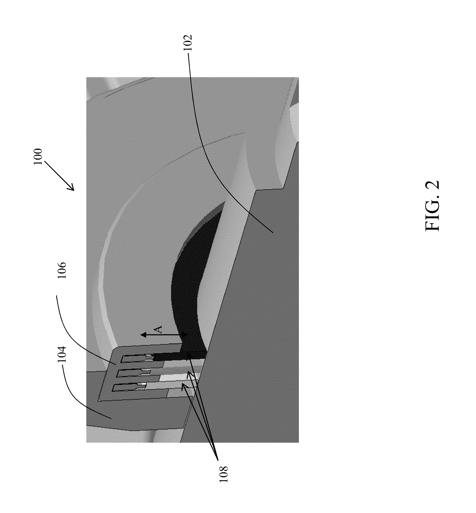
[0016]Turning to FIG. 2, a seal 100 according to an embodiment of the invention is shown. As shown in FIG...


PUM


Abstract

A sealing system that self-adjusts according to atmospheric conditions is disclosed. The sealing system includes an annular seal casing mounted on a stationary component, the annular seal casing positioned such that a rotating component extends therethrough, at least one annular sealing agent configured to radially move with respect to the rotating component between a sealed position and an unsealed position, at least one sensor for gathering atmospheric data, and at least one micro-mechanism configured to control the at least one annular sealing agent based on the atmospheric data.

Description

BACKGROUND OF THE INVENTION[0001]The invention relates generally to rotating body technology. More particularly, the invention relates to a seal that self-adjusts according to atmospheric conditions.[0002]Rotating bodies, such as rotors, are used in many different types of mechanical and electrical elements, including generators, motors and other similar devices. A mechanical seal assembly is commonly used on a rotating shaft of a motor enclosed in a motor housing, with the shaft projecting through a seal housing adjacent the motor housing to prevent contaminants from migrating along the shaft and entering the seal and motor housings. Different environmental or atmospheric conditions necessitate different protection levels. Therefore, different seals must be used for different protection levels according to different regulatory standards, environmental changes, or for other reasons. In addition, known seals are contact seals, i.e., the seal is in constant contact with the rotor, and...

Claims


Application Information

Patent Timeline
IPC IPC(8): F04D29/08F16J15/16
CPCF16J15/445F16J15/3296
Inventor RAI, MANDAR RANGANATHMAHAJAN, SACHIN VITTHALNAMANNAVAR, GIREESH ANANTACHARYA
Owner GENERAL ELECTRIC CO
Why Eureka
Try Eureka