

Systems and Methods of Antenna Orientation in a Point-To-Point Wireless Network
a wireless network and wireless network technology, applied in the field of wireless network systems, can solve the problems of link fading, significant attenuation of signals, and increased difficulty in aligning one or both antennas to achieve point-to-point communication
- Summary
- Abstract
- Description
- Claims
- Application Information
AI Technical Summary
Benefits of technology
Problems solved by technology
Method used
Image

Examples
Embodiment Construction
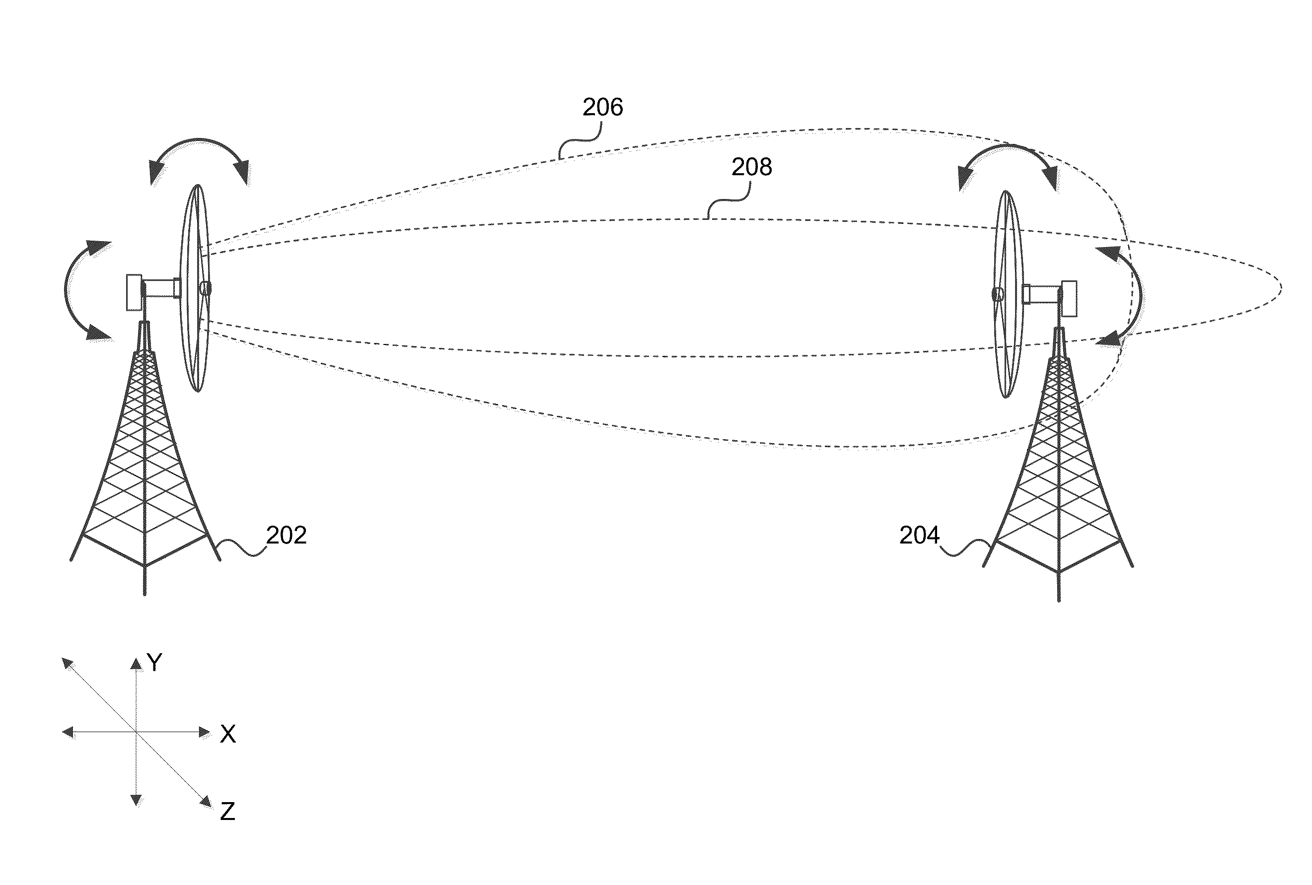
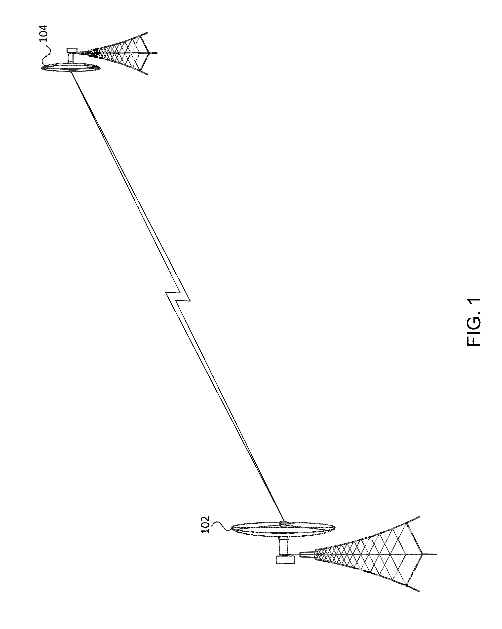
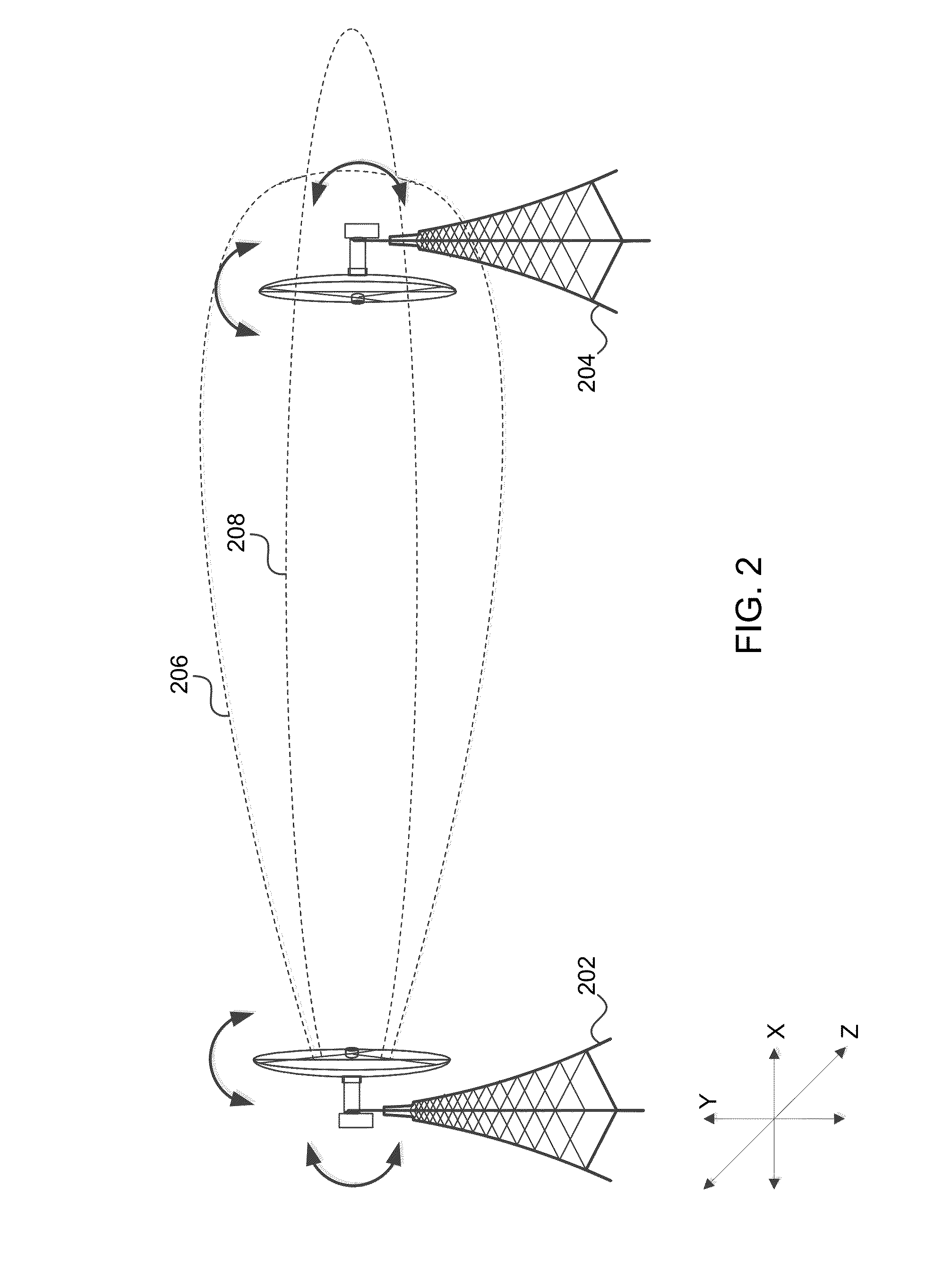
[0007]An exemplary method comprises positioning a first antenna to receive a first signal from a second antenna, the second antenna comprising energy absorbing material that functions to expand beamwidth, receiving the first signal from the second antenna, detecting a plurality of gains based on the first signal, repositioning the first antenna relative to the second antenna to a position associated with an acceptable gain based on the first signal, removing at least some of the energy absorbing material from the second antenna to narrow the beamwidth of the second antenna, receiving, by the first antenna, a second signal from the second antenna, detecting a plurality of gains based on the second signal, and repositioning the first antenna relative to the second antenna to a position associated with an increased gain of the plurality of gains based on the second signal, the increased gain being greater than the acceptable gain.
[0008]In various embodiments, repositioning the first an...
PUM
 Abstract
Description
Claims
Application Information