Plasma torch and retaining cap with fast securing threads

a technology of retaining cap and thread, which is applied in the field of plasma torch, can solve the problems of difficult and costly manufacture of components, difficult installation and removal of components of the torch,

Active Publication Date: 2013-02-21
ILLINOIS TOOL WORKS INC
View PDF6 Cites 27 Cited by
  • Summary
  • Abstract
  • Description
  • Claims
  • Application Information

AI Technical Summary

Problems solved by technology

Such components may be difficult and costly to manufacture.
Additionally such components may be difficult to install in and remove from the torch, while remaining secure during operation of the torch.

Method used


Image

  • Plasma torch and retaining cap with fast securing threads
  • Plasma torch and retaining cap with fast securing threads
  • Plasma torch and retaining cap with fast securing threads

Examples


Embodiment Construction

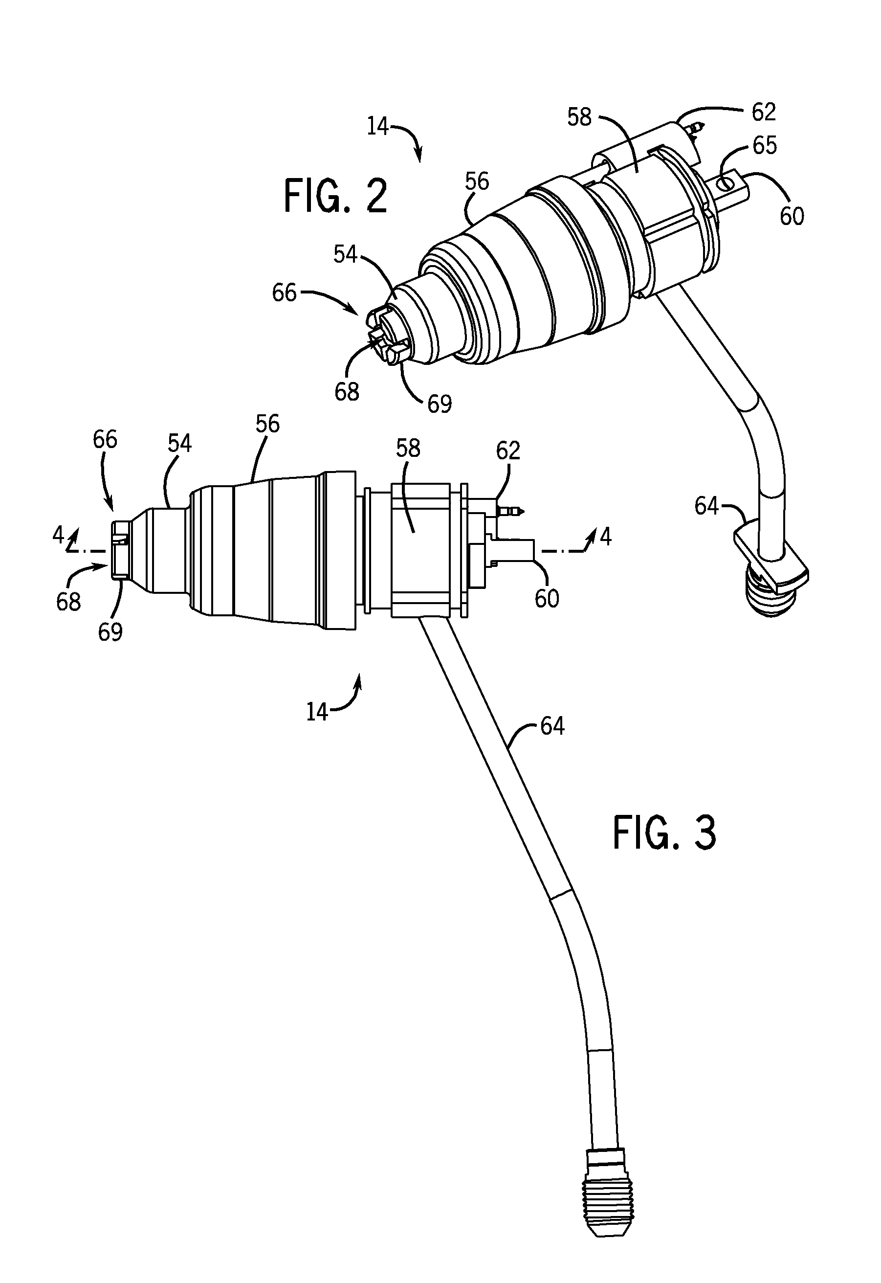
[0015]As described further below, embodiments of the invention include a plasma torch retaining cap having multiple start threads with a thread angle greater than 60°. The retaining cap may be installed on and removed from a torch body having corresponding threads for engaging the multiple start threads of the retaining cap. The retaining cap may be installed or removed in about a single 360° rotation of the cap, e.g., slightly more or slightly less than a 360° rotation. The multiple start thread with the thread angle of greater than 60° may provide easier installation and removal of the cap, and the thread may provide resistance to over-tightening, and binding, such as due to dirt and debris build-up in the threads. Moreover, the selected thread angle improves the threaded locking forces to minimize or prevent inadvertent loosening of the retaining up during operation of the torch

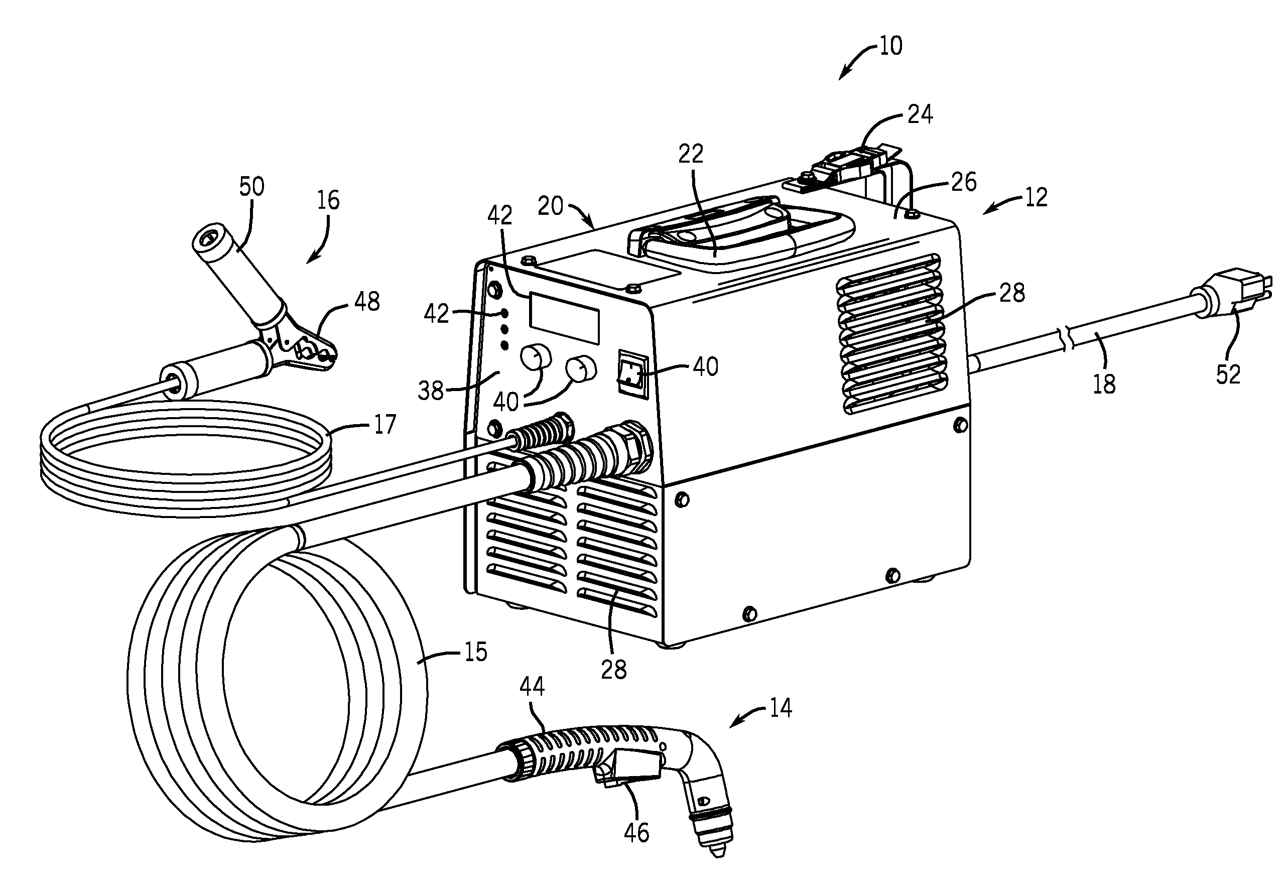
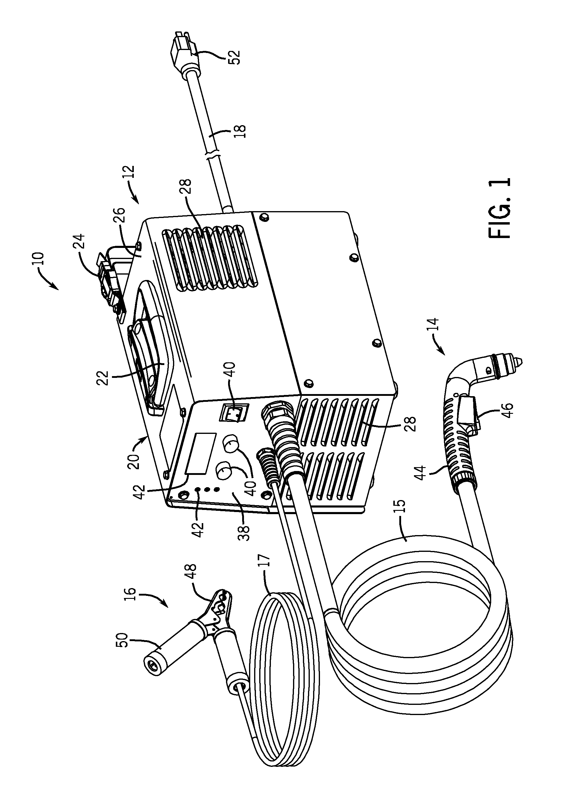
[0016]With the foregoing in mind, FIG. 1 is a perspective view illustrating an embodiment of a portable...


PUM

PropertyMeasurementUnit
thread angleaaaaaaaaaa
widthaaaaaaaaaa
widthaaaaaaaaaa

Abstract

A retaining cap for a plasma torch is provided that includes fast securing threads. The retaining cap includes internal threads that couple to external threads of a torch body of the plasma torch. The internal and external threads may be multiple start threads having a thread angle greater than 60°. Plasma torches and plasma cutting systems are also provided.

Description

BACKGROUND[0001]The invention relates generally to plasma cutting systems and, more particularly, to a plasma torch for such systems.BRIEF DESCRIPTION[0002]A plasma cutting system creates plasma (from high temperature ionized gas) to cut metal or other electrically conductive material. In general, an electrical arc converts a gas (e.g., compressed air) into plasma, which is sufficiently hot to melt the work piece while the pressure of the gas blows away the molten metal. The electrical arc is initiated in a plasma torch, and gas flows through the torch. A plasma torch may include a number of components that are used for various functions in the torch. Such components may be difficult and costly to manufacture. Additionally such components may be difficult to install in and remove from the torch, while remaining secure during operation of the torch.DRAWINGS[0003]These and other features, aspects, and advantages of the present invention will become better understood when the following...

Claims


Application Information

Patent Timeline
Patent Type & Authority Applications(United States)
IPC IPC(8): B23K10/00
CPCB23K9/013B23K9/287H05H2001/3457H05H1/34B23K10/00H05H1/3457
Inventor LEITERITZ, NATHAN GERALDCROWE, GEORGE ARTHUR
Owner ILLINOIS TOOL WORKS INC
Why Eureka
Try Eureka