Hardness tester

Active Publication Date: 2013-02-28
MITUTOYO CORP
View PDF5 Cites 8 Cited by
  • Summary
  • Abstract
  • Description
  • Claims
  • Application Information

AI Technical Summary

Problems solved by technology

However, in the method displaying only the partial image G3, only the area within the rectangular view B (one portion of the image) can be displayed, and so manual reading cannot

Method used


Image

  • Hardness tester
  • Hardness tester
  • Hardness tester

Examples


Example

[0026]The particulars shown herein are by way of example and for purposes of illustrative discussion of the embodiments of the present invention only and are presented in the cause of providing what is believed to be the most useful and readily understood description of the principles and conceptual aspects of the present invention. In this regard, no attempt is made to show structural details of the present invention in more detail than is necessary for the fundamental understanding of the present invention, the description is taken with the drawings making apparent to those skilled in the art how the forms of the present invention may be embodied in practice.

[0027]Hereafter, a hardness tester according to the present embodiment will be described in detail with reference to the drawings.

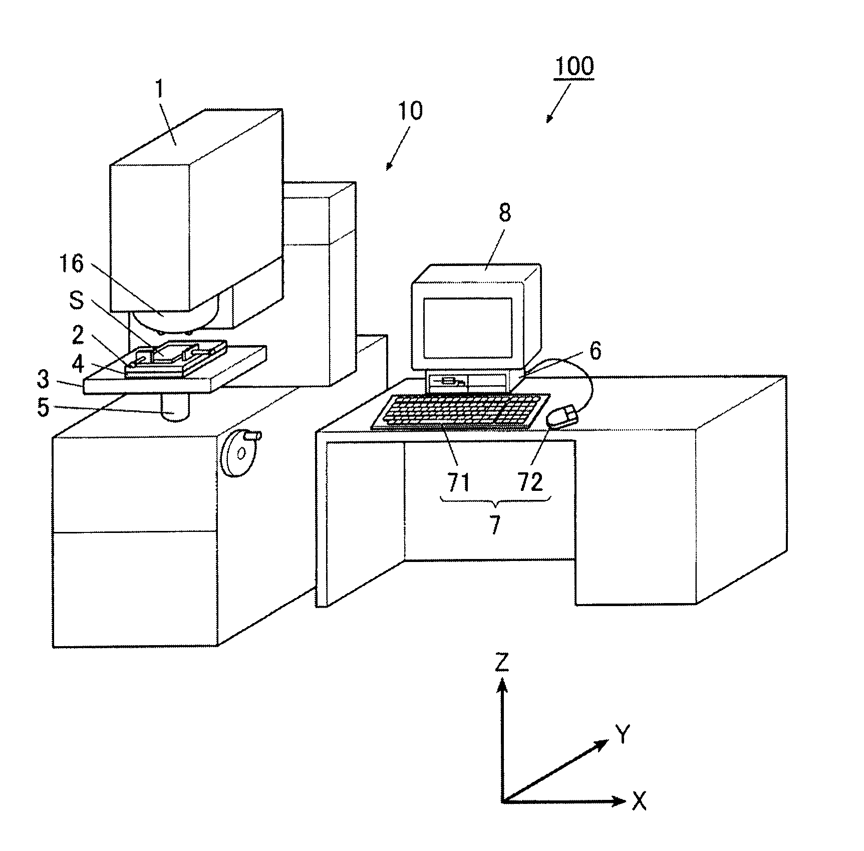
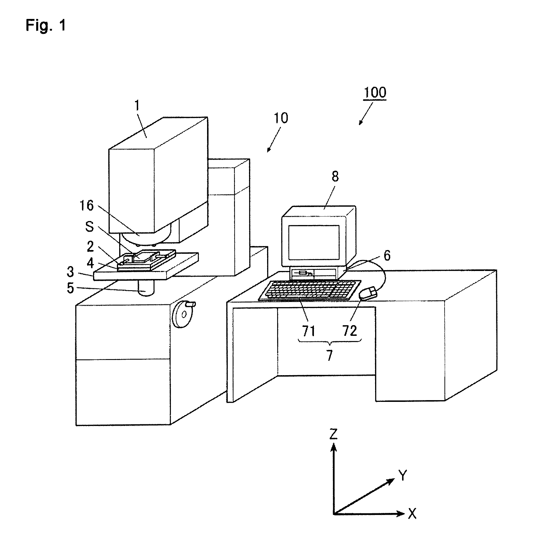
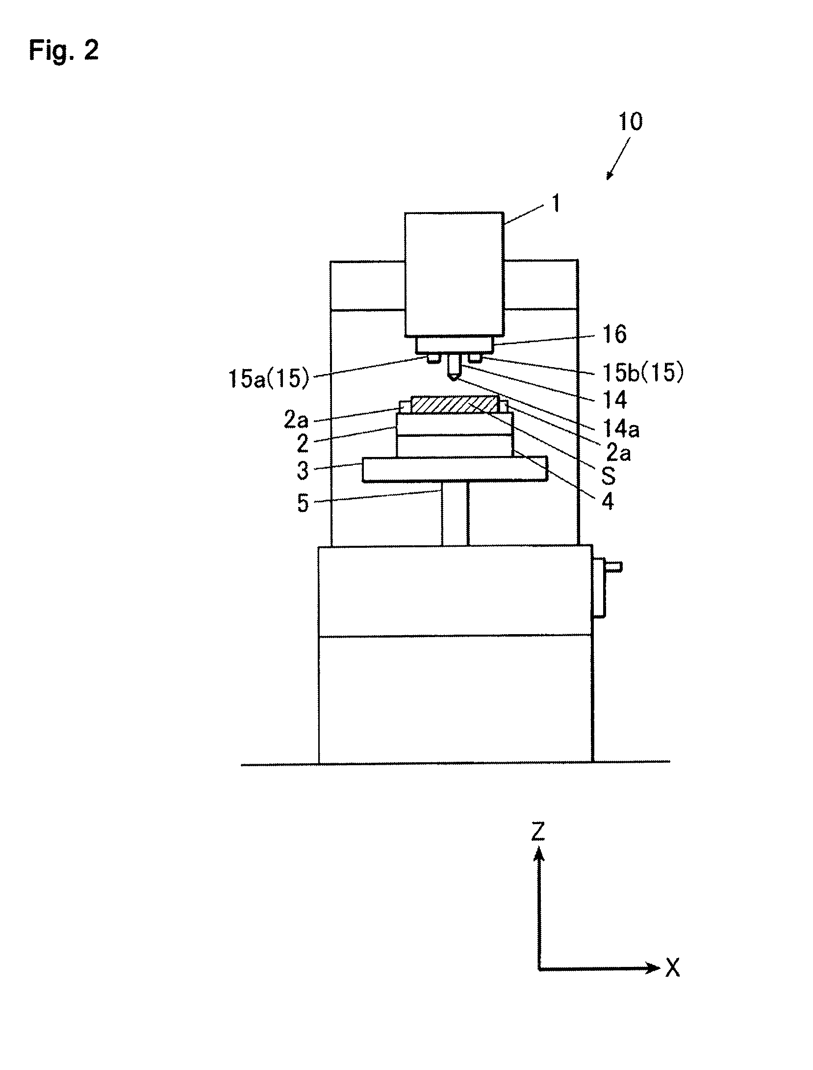
[0028]First, a configuration of a hardness tester 100 according to the present embodiment is described. Furthermore, in the following description, as shown in FIG. 1, left and right directions of th...


PUM


Abstract

A hardness tester includes a CCD camera, a monitor, a clipper (a CPU and a clipping program), and a display controller (the CPU and a display control program). The CCD camera captures an image of an indentation formed on a surface of a specimen via field lenses. The monitor displays the image of the indentation captured by the CCD camera. The clipper clips a plurality of regions from the image of the indentation captured by the CCD camera, the regions containing predetermined measurement points. The display controller simultaneously displays on the monitor images of the plurality of regions clipped by the clipper.

Description

CROSS-REFERENCE TO RELATED APPLICATIONS[0001]The present application claims priority under 35 U.S.C. §119 of Japanese Application No. 2011-188460, filed on Aug. 31, 2011, the disclosure of which is expressly incorporated by reference herein in its entirety.BACKGROUND OF THE INVENTION[0002]1. Field of the Invention[0003]The present invention relates to a hardness tester.[0004]2. Description of Related Art[0005]Conventionally, a hardness tester is known in which an indentation is formed by pressing an indenter into a surface of a specimen, and hardness of the specimen is measured based on dimensions of the indentation (see, for example, Related Art 1). For example, when a Vickers hardness tester is used to measure the hardness of the specimen, horizontal-direction alignment of the specimen is performed such that the formation position of the indentation in the surface of the specimen is directly below the indenter, and height-direction alignment (focusing) is performed on the formatio...

Claims


Application Information

Patent Timeline
IPC IPC(8): G01N3/48
CPCG01N3/068G06T7/0002G01N3/40G01N2203/0647G01N3/42
Inventor ARIGA, KOZO
Owner MITUTOYO CORP
Why Eureka
Try Eureka