Transparent display structure

a display structure and transparent technology, applied in the field of display structures, can solve the problems of high installation cost, limited style, low versatility of application, etc., and achieve the effect of low construction cost and high transparency

Inactive Publication Date: 2013-02-28
POLYTRON TECH
View PDF1 Cites 26 Cited by
  • Summary
  • Abstract
  • Description
  • Claims
  • Application Information

AI Technical Summary

Benefits of technology

[0006]One object of the present invention is to provide a transparent display structure with high transparency and be directly used as an outdoor glass wall or an indoor display divider of the architectural field so that the construction of the glass wall can be finished at the same time the transparent display structure is installed, providing the benefit of low construction cost.
[0007]One object of the present invention is to provide a transparent display structure opening for planar or curved shape design, thereby affording high application versatility.
[0008]One object of the present invention is to provide a transparent display structure of which light strips are disposed inside a laminated glass or hollow glass, thereby being protected from water and dust and having higher stability.

Problems solved by technology

However, such display board mostly requires additional installation work on the external portion of the glass curtain or cement wall and would incur higher installation cost.
Also, the LEDs suffering from the exposure to the sun and rain of the external environment would inevitably be damaged or deteriorate, causing the life expectancy of the large-sized display board to be affected.
In another aspect, the conventional large-sized display board is constrained to be configured on the plane of the external wall of the building, and can only be designed as a flat board, which has limited style and little application versatility, and therefore has a low practical value.

Method used


Image

  • Transparent display structure
  • Transparent display structure
  • Transparent display structure

Examples


Embodiment Construction

[0016]The examples described herein are provided merely for purposes of illustration and are not intended to limit embodiments of the present invention.

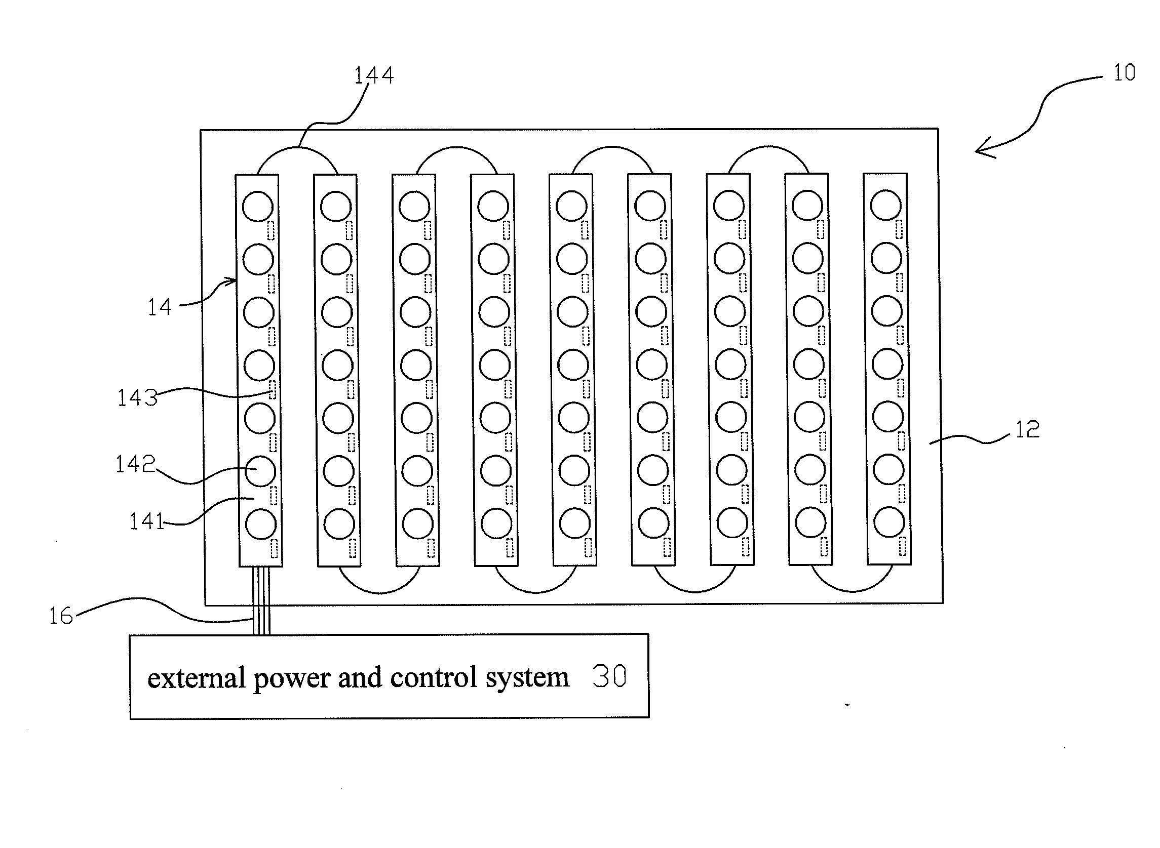
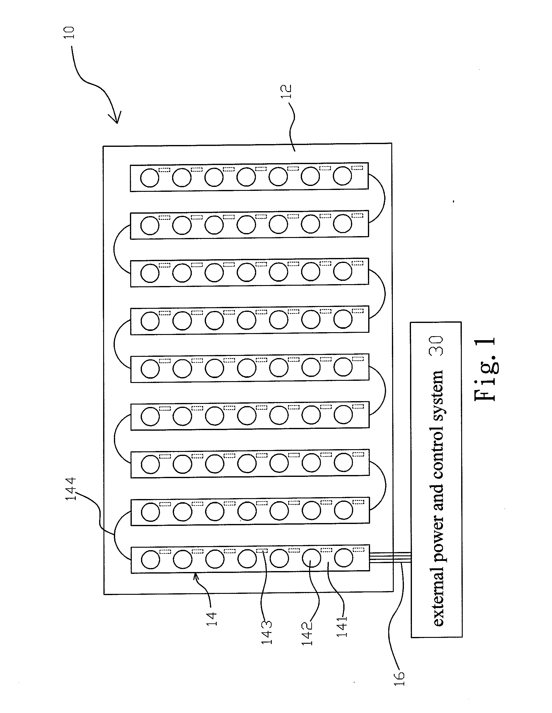
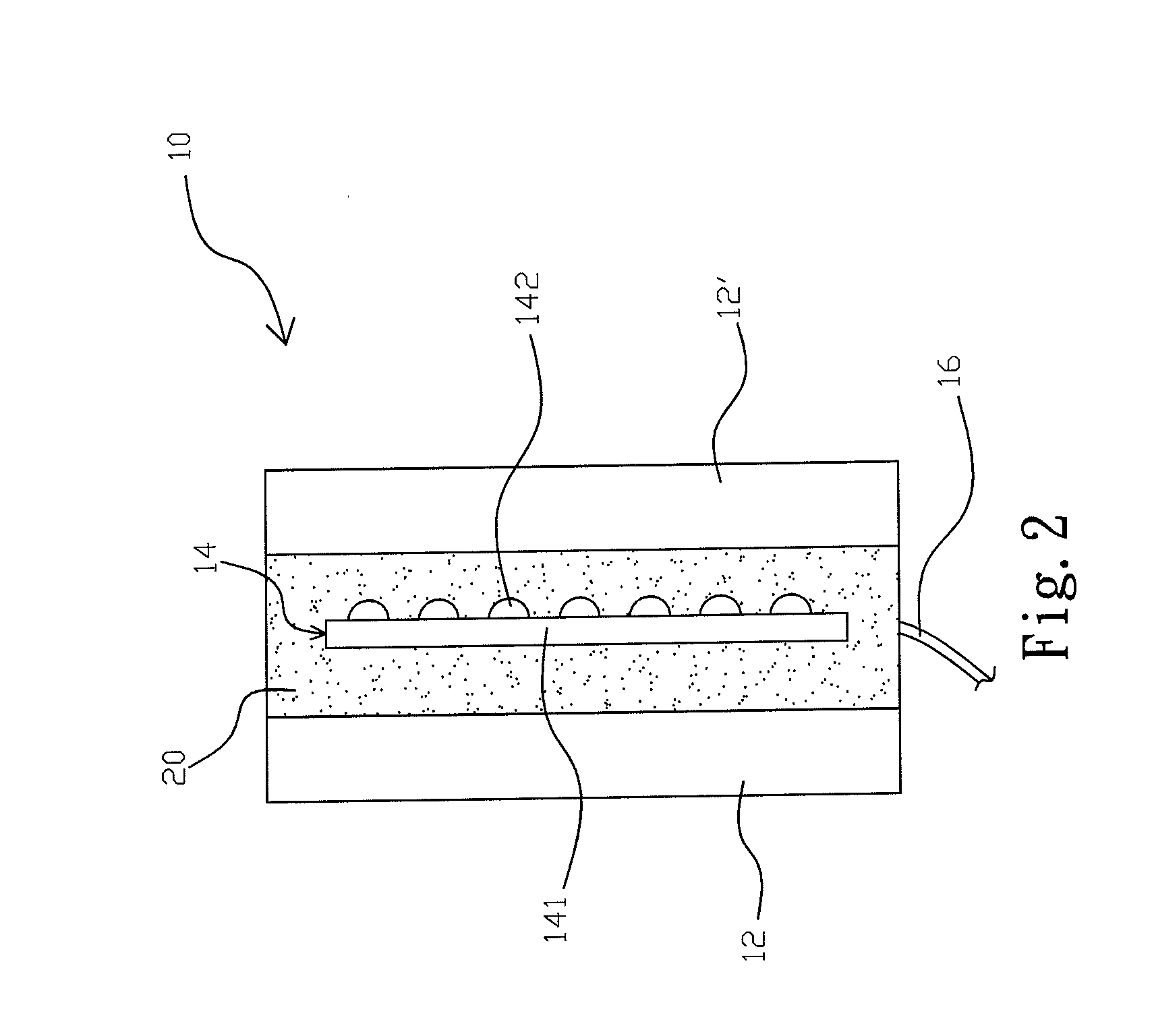
[0017]FIG. 1 is a schematic structural diagram of a transparent display structure according to a first embodiment. FIG. 2 is a schematic sectional diagram of the transparent display structure according to the first embodiment. Referring to FIG. 1 and FIG. 2, the transparent display structure 10 includes two transparent rigid base plates 12, 12′, a plurality of light strips 14 and an interlayer film 20. The two transparent rigid base plates 12, 12′ are configured spaced apart and parallel to each other. In this embodiment, the two transparent rigid base plates 12, 12′ are both flat boards. However, the present invention is not limited to be implemented in such way. The two transparent rigid base plates 12, 12′ may also be curved. The plurality of light strips 14 are arranged between the two transparent rigid base plates 12, 12′. The i...


PUM


Abstract

A transparent display structure includes two transparent rigid base plates, a plurality of light strips arranged therebetween and an interlayer film disposed between the two transparent rigid base plates and light strips. The plurality of light strips may also be disposed on an inner surface of the one of the transparent rigid base plates, and the interlayer film be disposed on the peripheries of the inner surfaces of the two transparent rigid base plates facing against each other. The transparent display structure can be directly used as an external wall, an outdoor display board or an indoor display divider of the architectural field. Also, the transparent display structure is open to planar shape design and curved shape design, thereby having high application versatility.

Description

BACKGROUND OF THE INVENTION[0001]1. Field of the Invention[0002]The present invention relates to a display structure, and more particularly to a transparent display structure constructed by transparent rigid base plates holding a plurality of light strips therebetween.[0003]2. Description of the Prior Art[0004]Nowadays many buildings adopt transparent glass curtain for the sake of appearance and lighting. Installing a large-sized display board on the glass curtain to increase the added value of the building has become a new advertisement style trend. Conventionally, a large-sized display board such as an electronic LED display board uses various array arrangements of LEDs to achieve the effect of variable patterns or direct image play. However, such display board mostly requires additional installation work on the external portion of the glass curtain or cement wall and would incur higher installation cost. Also, the LEDs suffering from the exposure to the sun and rain of the extern...

Claims


Application Information

Patent Timeline
Patent Type & Authority Applications(United States)
IPC IPC(8): F21S4/00
CPCG09F19/226G09F9/33
Inventor YU, SAMCHENG, DALONG
Owner POLYTRON TECH
Why Eureka
Try Eureka