Connector

Active Publication Date: 2013-02-28
YAZAKI NORTH AMERICA
View PDF10 Cites 5 Cited by
  • Summary
  • Abstract
  • Description
  • Claims
  • Application Information

AI Technical Summary

Benefits of technology

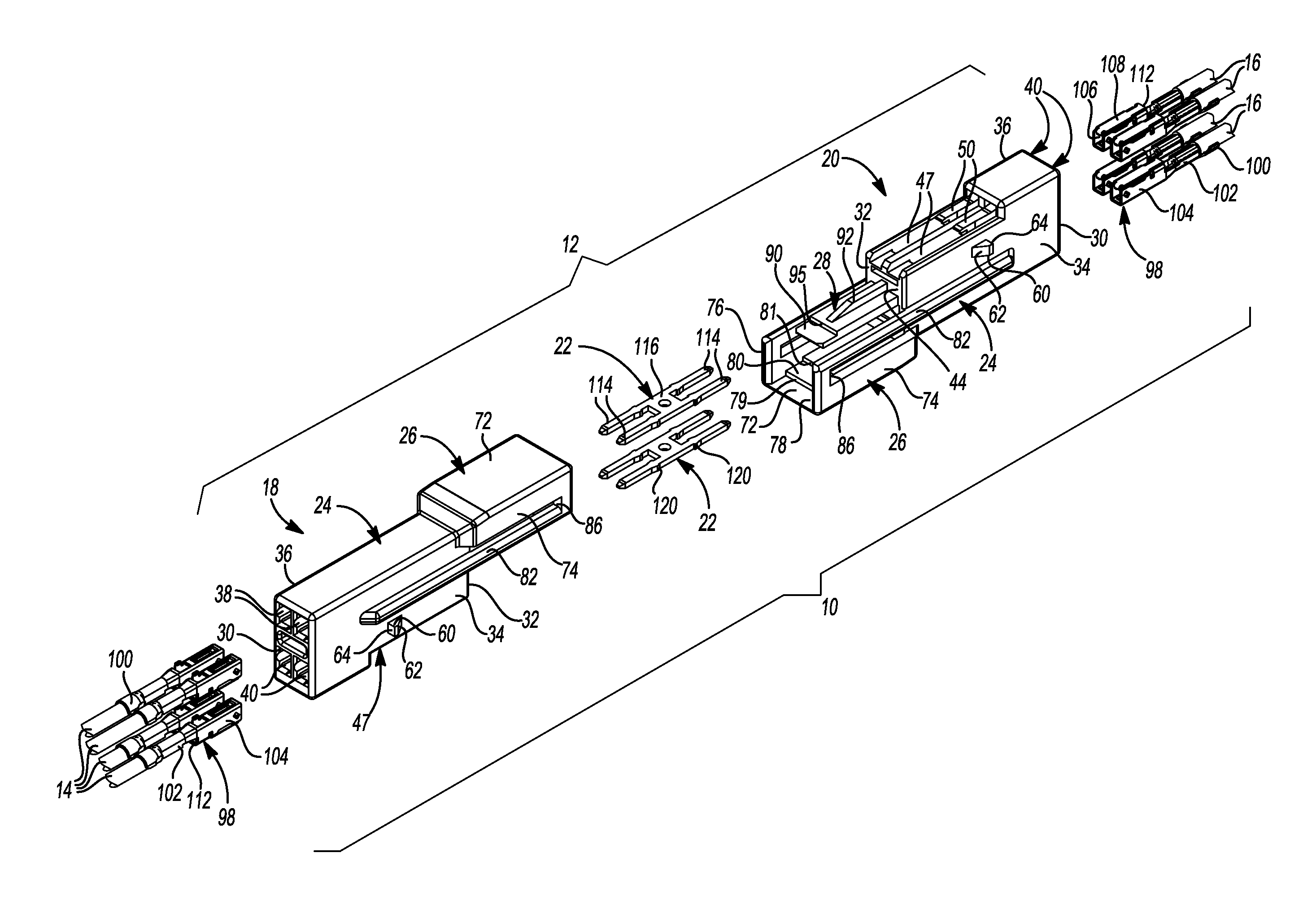
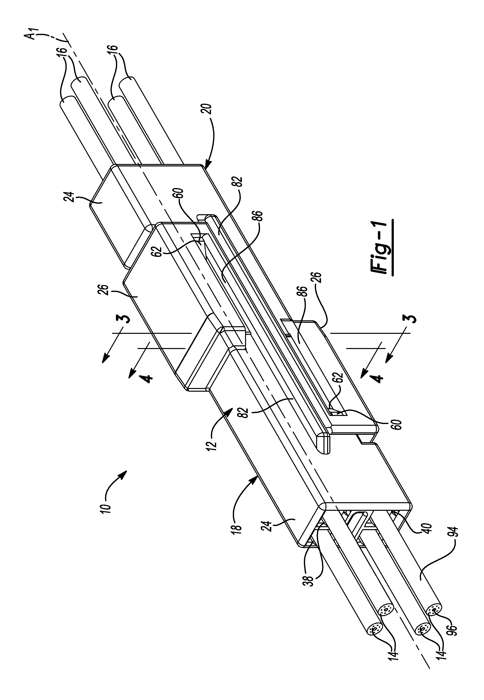
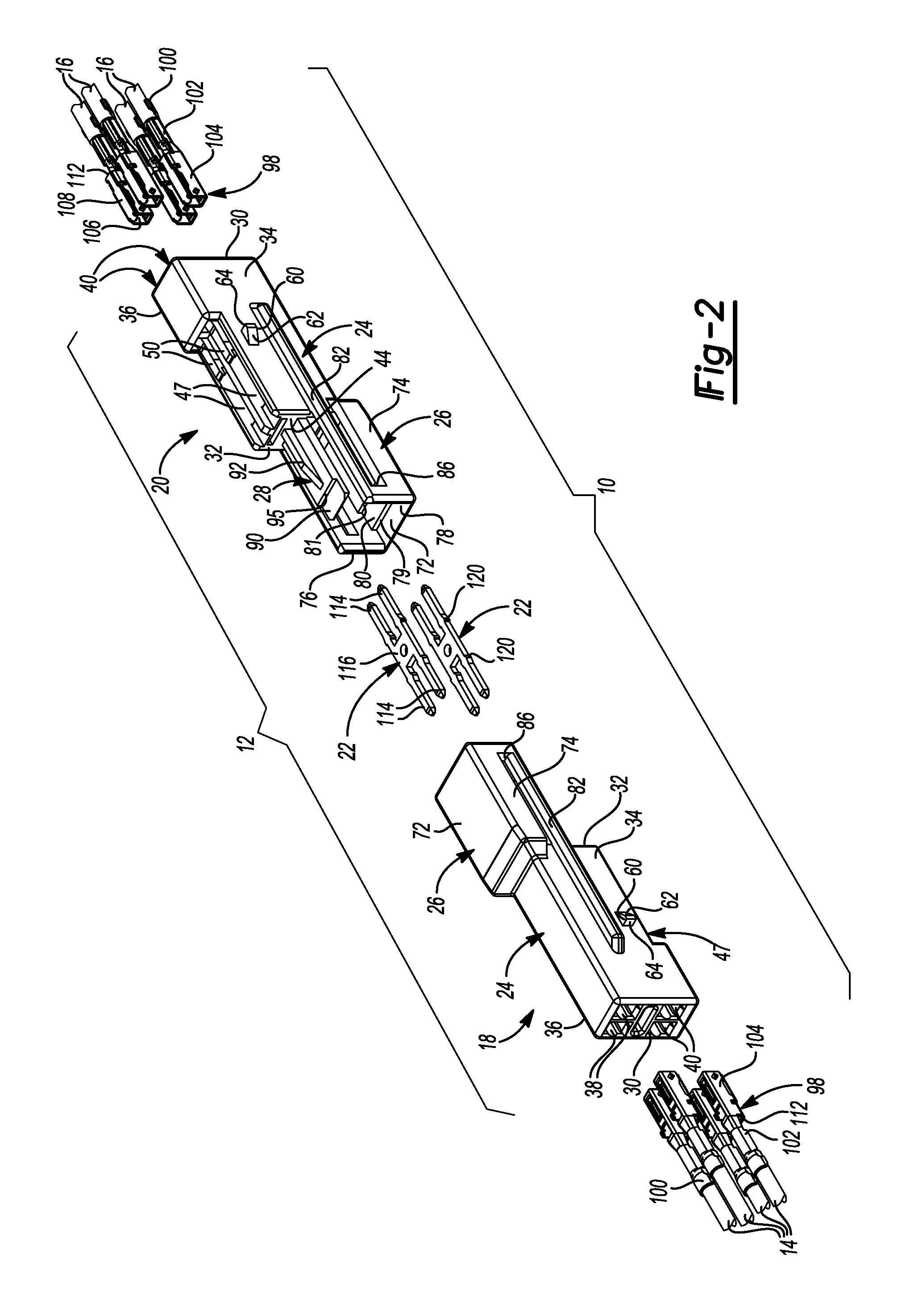
[0044]With the terminals 98 fully installed in the receptacles 38, 40, the first and second housings 18, 20 can be moved along the coupling axis A1 from the pre-set position (FIGS. 7-9) to the full-set position (FIGS. 1, 3, and 4). To move the first and second housings 18, 20 to the full-set position, the first and second housings 18, 20 may be slid along the rails 82, 84 toward one another such that the first latch members 91 that define the closed ends 89 of the first slots 86 resiliently deflect outwardly as they slide along the ramp surface 62 of an associated one of the first protrusions 60. Accordingly, it will be appreciated that the first latch members 91 can pass over the first protrusions 60 and then deflect inwardly (i.e., when the first and second housings 18, 20 are in the full-set position) so as to abut the latch surface 64 to limit withdrawal of the first and second housings 18, 20 from one another along the coupling axis A1. It will be appreciated that in some embodiments, the latch surface 64 may be angled relative to the first side 34

Problems solved by technology

While these typical connector assemblies have generally been adequate for electrically coupling two or more wires, the need to manufacture and i

Method used


Image

  • Connector
  • Connector
  • Connector

Examples


Embodiment Construction

[0020]Example embodiments will now be described more fully with reference to the accompanying drawings.

[0021]Example embodiments are provided so that this disclosure will be thorough, and will fully convey the scope to those who are skilled in the art. Numerous specific details are set forth such as examples of specific components, devices, and methods, to provide a thorough understanding of embodiments of the present disclosure. It will be apparent to those skilled in the art that specific details need not be employed, that example embodiments may be embodied in many different forms and that neither should be construed to limit the scope of the disclosure. In some example embodiments, well-known processes, well-known device structures, and well-known technologies are not described in detail.

[0022]The terminology used herein is for the purpose of describing particular example embodiments only and is not intended to be limiting. As used herein, the singular forms “a,”“an,” and “the” ...


PUM


Abstract

A connector is provided that may include first and second housings. The first housing may include a first body and a lock arm. The first body may include a first receptacle. The lock arm may be pivotably coupled to the first body. The second housing may include a second body having a second receptacle and a support member. The first and second housings may be engageable with each other in a first position and a second position and movable relative to each other from the first position to the second position. The lock arm may be deflectable relative to the support member when the first and second housings are in the first position. The support member may restrict deflection of the lock arm when the first and second housings are in the second position.

Description

FIELD[0001]The present disclosure relates to a connector.BACKGROUND[0002]This section provides background information related to the present disclosure and is not necessarily prior art.[0003]Electrical connector assemblies may provide robust and convenient means for connecting one or more wires or electrical conductors to one or more other wires or electrical connectors for electrical communication therebetween. Typical connector assemblies include a male connector that is received into a female connector. While these typical connector assemblies have generally been adequate for electrically coupling two or more wires, the need to manufacture and inventory two different connector pieces (i.e., the male connector and the female connector) can be costly and can complicate assembly processes.SUMMARY[0004]This section provides a general summary of the disclosure, and is not a comprehensive disclosure of its full scope or all of its features.[0005]In one form, the present disclosure prov...

Claims


Application Information

Patent Timeline
IPC IPC(8): H01R13/62
CPCH01R13/4223H01R31/08H01R24/84
Inventor OSTERHART, MICHAEL PAULYOUNGLOVE, KENT EDWARD
Owner YAZAKI NORTH AMERICA
Why Eureka
Try Eureka