Folding wing tip and biased locking device

a locking device and wing tip technology, applied in aircraft control, wing adjustment, aircraft components, etc., can solve the problems of limiting the maximum aircraft span, affecting the stability of the aircraft, so as to achieve the effect of limited deflection of the wing tip devi

Active Publication Date: 2016-11-17
AIRBUS OPERATIONS LTD
View PDF3 Cites 6 Cited by
  • Summary
  • Abstract
  • Description
  • Claims
  • Application Information

AI Technical Summary

Benefits of technology

[0013]The biasing device may be configured such that if the wing tip device experiences a threshold load in the flight configuration, the biasing device allows at least a limited deflection of the wing tip device. This deflection may absorb the exc

Problems solved by technology

However, the maximum aircraft span is effectively limited by airport operating rules which govern various clearances required when maneuvering around the airport (such as the span and/or ground clearance required for gate entry and safe taxiway usage).
However, conventional locking mechanisms may not provide the secure fastening required for a folding wing tip.
In particular, we

Method used


Image

  • Folding wing tip and biased locking device
  • Folding wing tip and biased locking device
  • Folding wing tip and biased locking device

Examples


Embodiment Construction

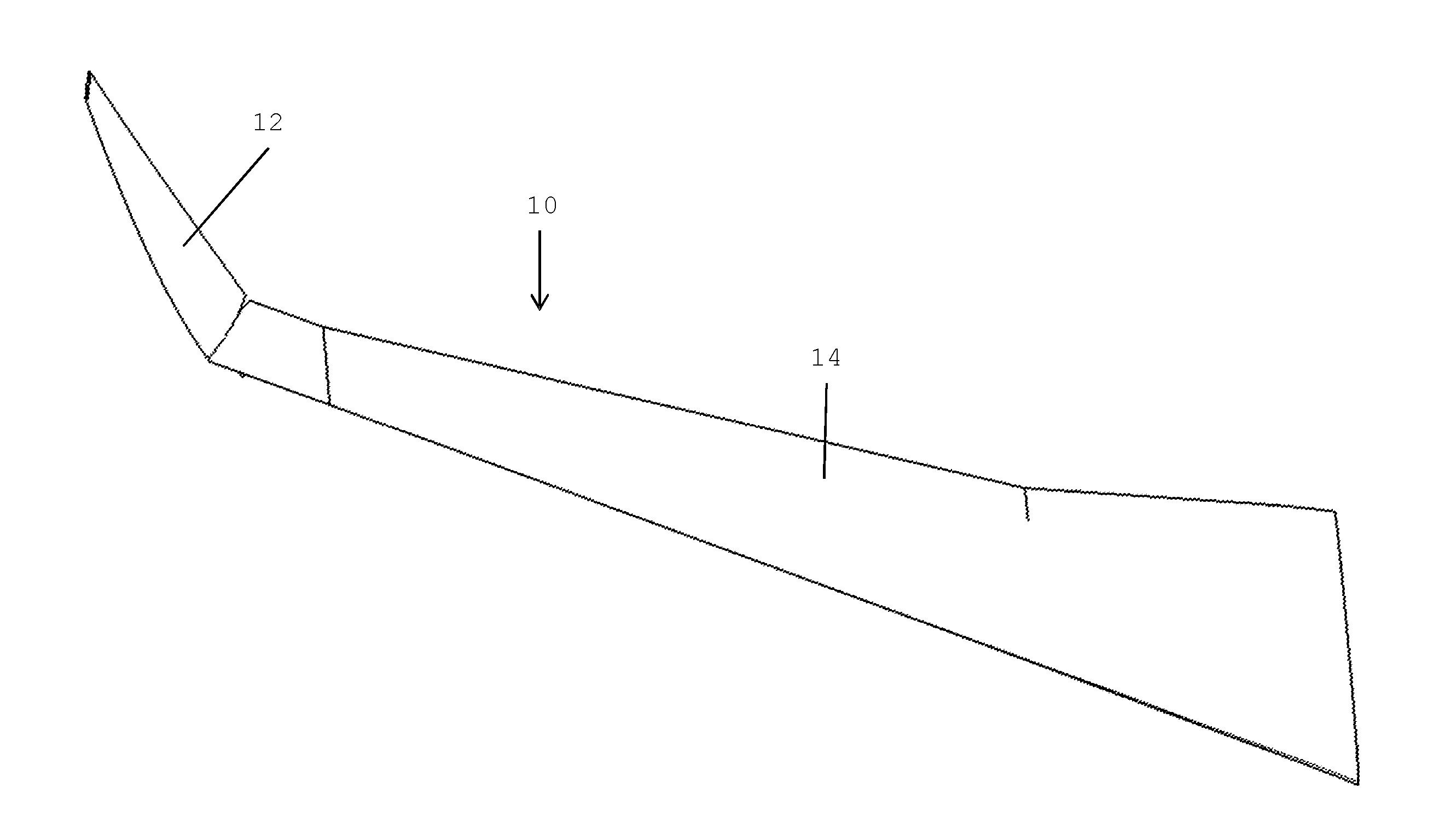
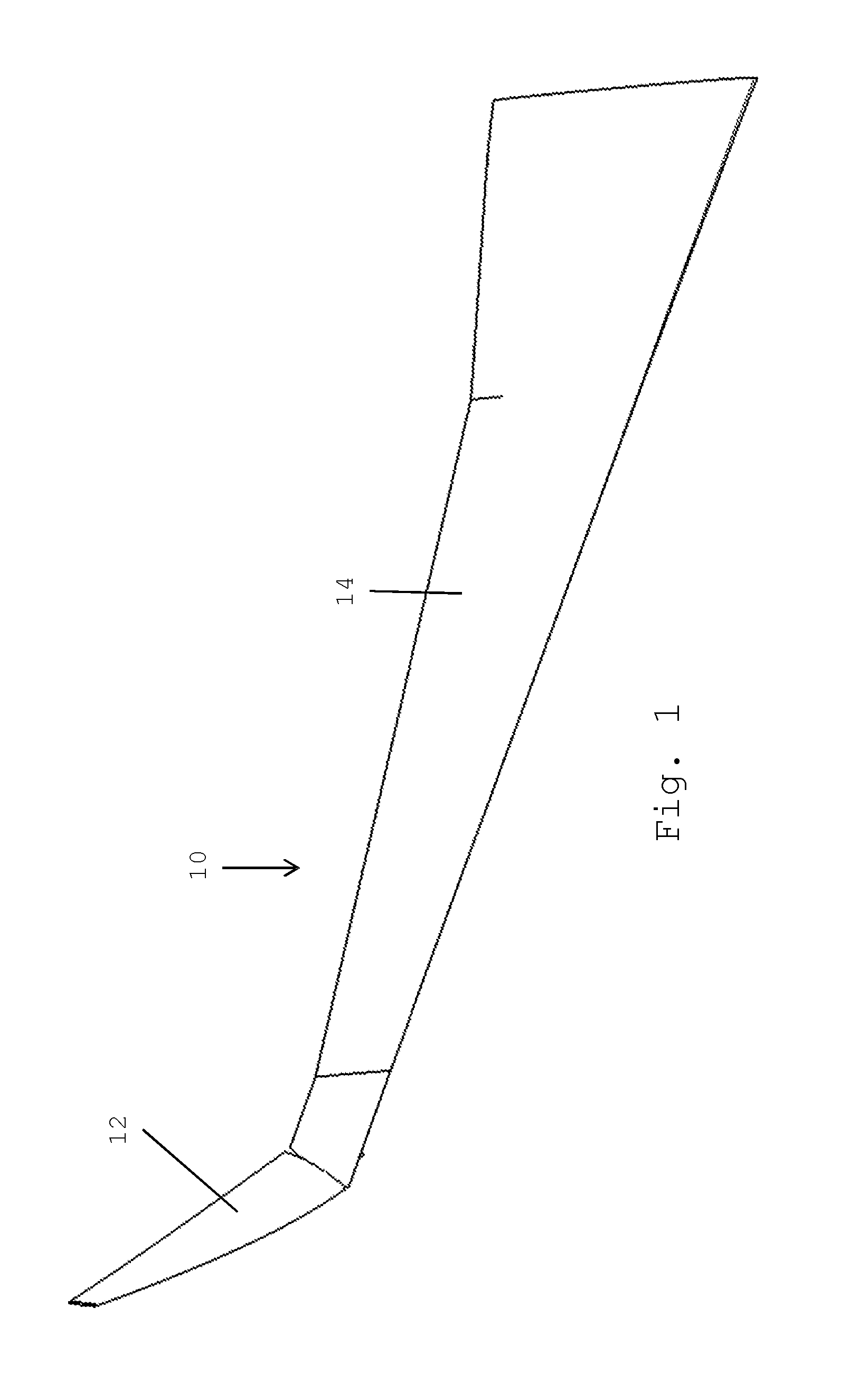
[0030]FIG. 1 shows an aircraft wing 10, comprising a folding wing tip device 12 and a fixed wing 14. The folding wing tip device 12 is connected to the outer edge of the fixed wing 14 by a hinge (not shown), and is movable between a flight configuration in which the wing tip device 12 is extended and increases the span of the wing 10, and a ground configuration, where the wing tip device 12 is moved away from the flight configuration and the span of the wing 10 is reduced. The wing 10 is shown in the ground configuration in FIG. 1.

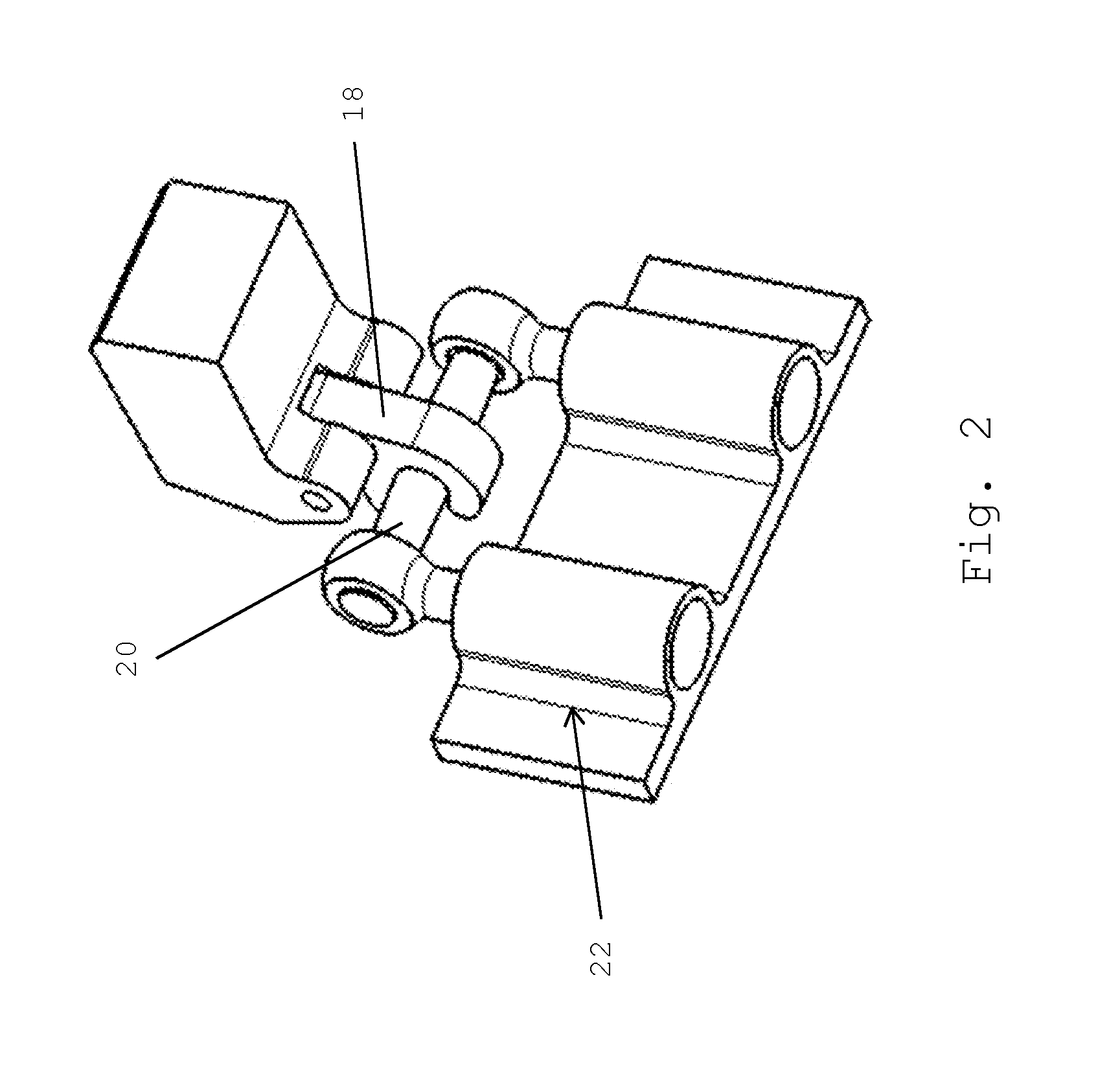
[0031]FIGS. 2 and 3 show the locking mechanism 16 comprising a locking hook 18, a locking pin 20, and a biasing device 22 associated with the locking pin 20. The biasing device 22 comprises a first support arm 24 and a second support arm 26 connected at each longitudinal end of the locking pin 20. Each support arm 24, 26, is associated with a helical spring 28, 30. The end of each support arm away from the locking pin includes an expanded stop 32, 34, enga...


PUM


Abstract

The invention provides an aircraft comprising an aircraft wing. The aircraft wing comprises a fixed wing and a wing tip device at the tip thereof, wherein the wing tip device is configurable between: (i) a locked flight configuration for use during flight and (ii) a ground configuration for use during ground-based operations, in which ground configuration the wing tip device is moved away from the flight configuration such that the span of the aircraft wing is reduced. The aircraft wing further comprises a locking mechanism for locking the folding wing tip device in the flight configuration. The locking mechanism comprises a locking hook associated with one of the folding wing tip device and the fixed wing, and a locking pin associated with the other of the folding wing tip device and the fixed wing, and a biasing device, wherein in the locked configuration the locking pin is engaged with the locking hook and the biasing device acts to preload the locking mechanism.

Description

BACKGROUND OF THE INVENTION[0001]There is a trend towards increasingly large passenger aircraft, for which it is desirable to have correspondingly large wing spans. However, the maximum aircraft span is effectively limited by airport operating rules which govern various clearances required when maneuvering around the airport (such as the span and / or ground clearance required for gate entry and safe taxiway usage).[0002]Therefore, folding wing tip devices have been introduced into passenger aircraft, where a wing tip device is movable between a flight configuration for use during flight, and a ground configuration for use during ground-based operations. In the ground configuration, the wing tip device is moved away from the flight configuration such that the span of the aircraft wing is reduced, thereby allowing use of existing gates and safe taxiway usage.[0003]In order to securely fasten the folding wing tip device in the flight configuration, one or more locking mechanisms must be...

Claims


Application Information

Patent Timeline
IPC IPC(8): B64C3/56
CPCB64C3/56B64C23/072Y02T50/10
Inventor HANCOCK, NICK
Owner AIRBUS OPERATIONS LTD
Why Eureka
Try Eureka