Provisional prosthetic component formed of multiple materials

a prosthetic component and multiple material technology, applied in the field of provisional prosthetic components, can solve the problems of shortening the recovery time of patients and accelerating healing, and achieve the effect of reducing the hardness of scratches

Inactive Publication Date: 2008-06-05
ZIMMER TECH INC
View PDF22 Cites 32 Cited by
  • Summary
  • Abstract
  • Description
  • Claims
  • Application Information

AI Technical Summary

Benefits of technology

[0008]The present invention relates to provisional prosthetic components for a medical device and the surgical methods for utilizing the same. In one embodiment, the provisional prosthetic component includes a first portion and a core. The first portion is capable of mating with another modular prosthetic component. The first portion of the provisional prosthetic component may have a scratch hardness which is less than the scratch hardness of the modular prosthetic component. This allows for the first portion to be placed in mating engagement with the prosthetic component without scratching or damaging the junction of the modular prosthetic component. Additionally, the core of the provisional prosthetic component may have a scratch hardness greater than the scratch hardness of the first portion of the provisional prosthetic component and / or a stiffness sufficient to minimize deflection of the provisional prosthetic component during trial reduction and range of motion testing.
[0009]Advantageously, the design of the present provisional component allows for the use of a non-provisional modular prosthetic component during trialing of the provisional components. This results from the present provisional prosthetic component providing a connection with the non-provisional modular prosthetic component which will not scratch or damage the junction of the non-provisional modular prosthetic component. Additionally, the present provisional component includes a core which is stiff enough to limit deflection of the present provisional component during trialing to provide an accurate representation of the relative position of the final, non-provisional prosthetic component.
[0012]In another form thereof, the present invention provides a method for trialing a prosthetic device including the steps of implanting a component of a modular prosthesis within a joint of a patient's body; attaching a provisional component to the component of the modular prosthesis, the provisional component having a body sized to replicate the orientation of at least one component of the modular prosthetic component, the body including a core formed of a core material; and a first portion overlying the core, the first portion having a provisional prosthetic junction surface sized and shaped to mate with a final modular prosthetic junction surface of the component of a modular prosthesis, the provisional prosthetic junction formed from a provisional material, the final modular prosthetic junction surface formed from a final modular prosthetic material, the provisional prosthetic material having a lower scratch hardness than the final modular prosthetic material, whereby interaction of the provisional prosthetic material with the final modular prosthetic material will more likely cause scratching of the provisional prosthetic material than the final modular prosthetic material, the core material having a stiffness greater than the provisional prosthetic material from which the provisional prosthetic junction surface is formed; reducing the joint, including the provisional component; evaluating the performance of the provisional component; and replacing the provisional component with a corresponding component of the modular prosthesis.

Problems solved by technology

This may shorten a patient's recovery time and expedite healing.

Method used


Image

  • Provisional prosthetic component formed of multiple materials
  • Provisional prosthetic component formed of multiple materials
  • Provisional prosthetic component formed of multiple materials

Examples


Embodiment Construction

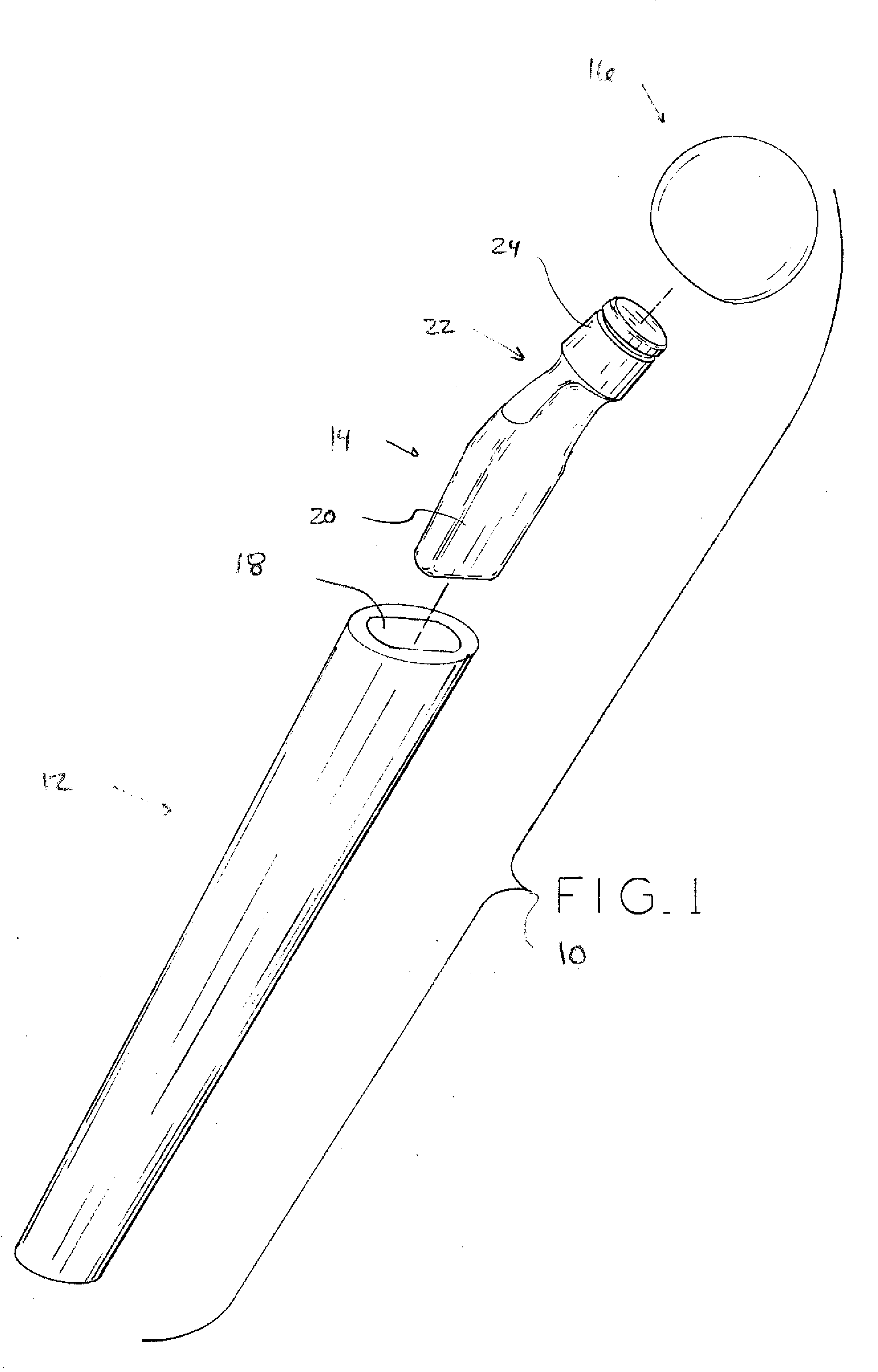
[0025]FIG. 1 depicts a modular prosthesis system as modular femoral prosthesis 10. Modular femoral prosthesis 10 includes stem 12, neck 14, and head 16. Stem 12 is designed to seat within the intramedullary canal of a femur and includes female tapered cavity 18. Neck 14 connects to stem 12 via insertion of male tapered portion20 into female tapered cavity 18. In use, upper portion 22 of neck 14 can extend from the intramedullary canal of the femur into the joint space of the hip. Neck 14 further includes second male taper 24 designed to mate with a female tapered cavity (not shown) within head 16. Head 16 replaces the natural femoral head and, once implanted, articulates against the natural acetabulum or an implanted acetabular prosthesis. To prepare the femur for insertion of stem 12, the upper portion of the femur is, in certain surgical techniques, resected and a series of broaches having an increasing diameter can be utilized to prepare the femur to receive modular femoral prost...


PUM


Abstract

The present invention relates to provisional prosthetic components for a medical device and the surgical methods for utilizing the same. In one embodiment, the provisional prosthetic component includes a first portion and a core. The first portion is capable of mating with another prosthetic component. The first portion of the provisional prosthetic component may have a scratch hardness which is less than the scratch hardness of the prosthetic component. This allows for the first portion to be placed in mating engagement with the prosthetic component without scratching or damaging the junction of the prosthetic component. Additionally, the core of the provisional prosthetic component may have a scratch hardness greater than the scratch hardness of the first portion of the provisional prosthetic component and / or a stiffness sufficient to minimize deflection of the provisional prosthetic component during trial reduction and range of motion testing.

Description

BACKGROUND[0001]1. Field of the Invention[0002]The present invention relates to a provisional prosthetic component for a medical device and the surgical methods for utilizing the same.[0003]2. Description of the Related Art[0004]Prostheses are commonly utilized to repair and / or replace damaged bone and tissue in the human body. For example, a hip prosthesis may be implanted to replace damaged or destroyed bone in the femur and / or acetabulum and recreate the natural, anatomical articulation of the hip joint. To implant a prosthesis, orthopedic surgery is performed which requires the creation of an incision in the skin of the patient and may necessitate the retraction of large portions of surrounding tissue to provide the surgeon with sufficient access to the surgical site. However, some orthopedic surgeries are performed utilizing minimally invasive techniques. When these techniques are utilized, a minimally invasive surgery is performed which may require only a small incision and ve...

Claims


Application Information

Patent Timeline
Patent Type & Authority Applications(United States)
IPC IPC(8): A61F2/36A61F2/30
CPCA61F2/30965A61F2310/00029A61F2/3609A61F2/3662A61F2/4684A61F2002/30016A61F2002/30332A61F2002/30334A61F2002/30341A61F2002/30354A61F2002/3038A61F2002/30448A61F2002/30492A61F2002/30594A61F2002/30604A61F2002/30616A61F2002/30713A61F2002/30822A61F2002/30836A61F2002/30904A61F2002/30957A61F2002/3611A61F2002/3625A61F2002/365A61F2002/3652A61F2002/481A61F2220/0025A61F2220/0033A61F2220/005A61F2250/0019A61F2250/006A61F2250/0064A61F2250/0087A61F2310/00017A61F2310/00023A61F2/36A61F2002/30339A61F2002/30331A61F2002/3071A61F2/481
Inventor SCHLOTTERBACK, RYAN D.BANERJEE, BARISHSMYTHE, RANDY G.
Owner ZIMMER TECH INC
Why Eureka
Try Eureka