Electrical connection terminal

a technology of electric connection and terminal, which is applied in the direction of fixed connection, coupling device connection, transportation and packaging, etc., can solve the problems of unsecure clamping of said conductor, high complexity of contact frame design, and insufficient guidance, so as to prevent damage to leaf springs and/or push elements, the effect of simple handling

Active Publication Date: 2013-11-26
WAGO VERW GMBH
View PDF4 Cites 37 Cited by
  • Summary
  • Abstract
  • Description
  • Claims
  • Application Information

AI Technical Summary

Benefits of technology

[0005]The object of the invention is to provide an electrical connection terminal for the connection of an electrical conductor, which electrical connection terminal ensures secure clamping of the electrical conductor and at the same time has a simple structure.DISCLOSURE OF THE INVENTION
[0007]Simple and effective conductor guidance is achieved on account of the funnel-like conductor insertion region being composed of the insulating material housing and the contact frame or being formed by these two components, it being possible, in particular, for the contact frame to be of very simple, compact and material-saving design. The conductor insertion region can therefore also be varied in a simple manner as required and matched to the various requirements since the two components can be considered to be separate from one another.
[0013]In each case one run-on slope which is directed toward the outer face of the electrical terminal is integrally formed on the leaf springs, said run-on slopes being turned out in relation to one another in the form of a funnel. The clamping point can be opened by means of these run-on slopes by it being possible for the leaf springs to be pushed apart in a simplified manner via the run-on slopes by means of an operating means. In this way, inserted electrical conductors can either be easily removed or inserted in a simplified manner. Therefore, multi-wire conductors, in particular, can be used for this electrical connection terminal.
[0015]In a further preferred embodiment, the contact frame is connected to the insulating material housing by means of at least one latching connection. This creates a permanent fixed connection between the contact frame and the insulating material housing which is simple to handle.
[0016]In order to effectively prevent the leaf springs and / or the push element from being damaged, in particular fractured, an overload protection means is provided for said component in one preferred embodiment. In this case, the deflection of the leaf springs can advantageously be limited by side walls and / or intermediate walls of the insulating material housing. It is further advantageous for the deflection of the push element arm of the push element to be limited by abutment of the push element arm against at least one leaf spring. These embodiments make it possible to provide overload protection without significantly adapting the electrical connection terminal, and are therefore cost-effective.

Problems solved by technology

A conductor to be inserted is not adequately guided in the region of the leaf springs in particular, and this may lead to unsecure clamping of said conductor.
The contact frame is therefore of highly complicated design.
A leaf spring tongue in each case projects from the lower face and the upper face of the tunnel-like component offset in the direction of the tunnel interior, it being possible for an electrical conductor to be accommodated in a clamped manner between the ends of the leaf springs, and therefore a relatively complicated design of the contact frame with a high metal content is provided in this case too.

Method used


Image

  • Electrical connection terminal
  • Electrical connection terminal
  • Electrical connection terminal

Examples


Embodiment Construction

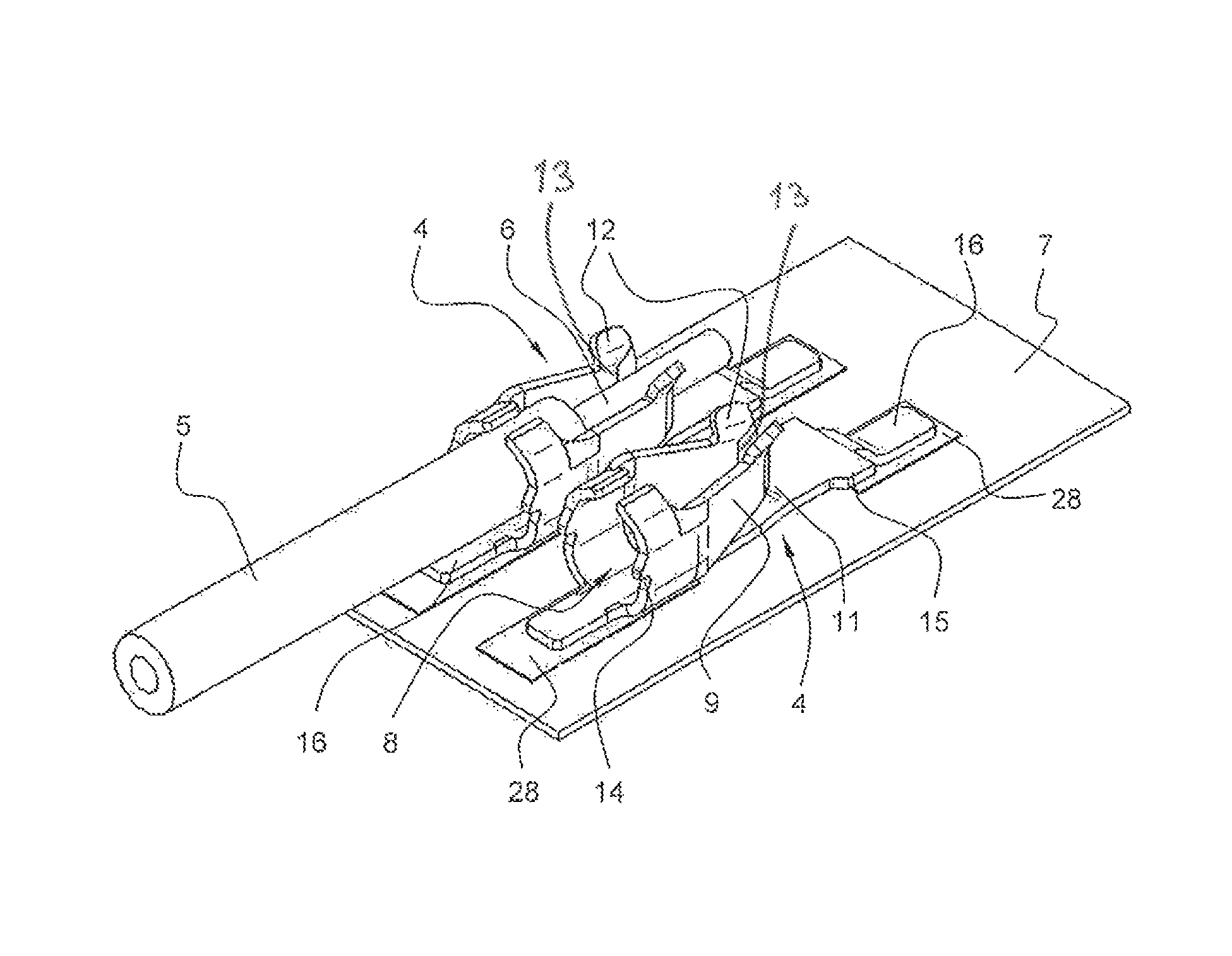
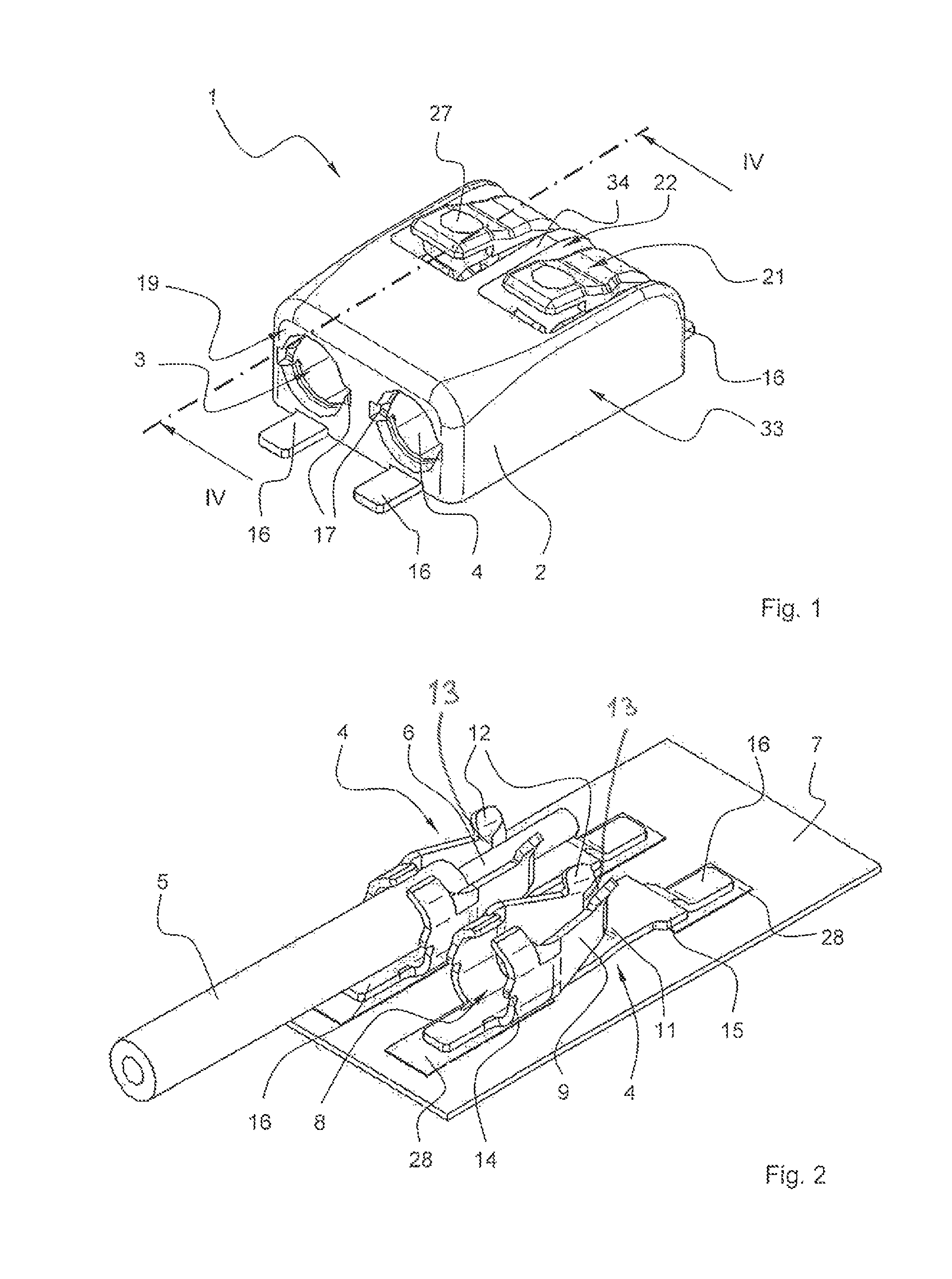
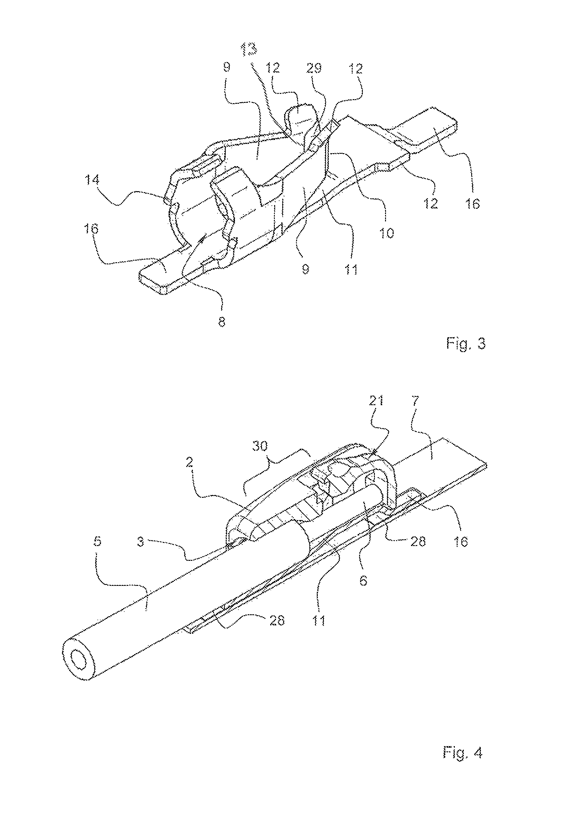
[0027]FIG. 1 shows an electrical connection terminal 1 according to the invention having an insulating material housing 2 in which a metal contact frame 4 is accommodated. The insulating material housing 2 has, at an end face 19, at least one conductor insertion opening 3 for the insertion of an electrical conductor 5 (FIG. 4). In the illustrated exemplary embodiment, the connection terminal 1 is of two-pole design with in each case one conductor insertion opening 3 and a contact frame 4 for each pole. However, the connection terminal may also have any other desired number of poles.

[0028]Also shown in FIG. 1 are connection regions 16 of the contact frame 4 which make contact with corresponding contact sections 28, for example conductor tracks, of a printed circuit board 7 (FIG. 2). In this case, the connection regions 16 are connected to the contact sections 28 in particular via solder connections (SMD solder connection), but a plug-type connection is also feasible. FIG. 2 shows the...


PUM


Abstract

An electrical connection terminal provides secure clamping of an electrical conductor and at the same time has a simple structure. Simple and effective conductor guidance is achieved on account of a funnel-like conductor insertion region being composed of an insulating material housing and a contact frame. The contact frame can be of very simple, compact and material-saving design.

Description

[0001]The invention relates to an electrical connection terminal for the clamping connection of at least one electrical conductor, having a contact frame which is accommodated in an insulating material housing and is stamped out from a flat metal material and is formed in the form of a channel with at least two side walls and a contact base, with the contact frame, for the purpose of forming a conductor clamping connection, having on each side wall in each case a leaf spring in the form of a tongue which is formed from the flat metal part and which is bent out of the plane of the flat metal part in such a way that the free end of the leaf spring forms a clamping edge which is directed toward the electrical conductor, and having a funnel-like conductor insertion region which tapers at least in sections in the direction of a clamping point which is formed by the clamping edge, with the conductor insertion region adjoining a conductor insertion opening in the insulating material housin...

Claims


Application Information

Patent Timeline
Patent Type & Authority Patents(United States)
IPC IPC(8): H01R11/22H01R13/11
CPCH01R4/4836H01R12/57H01R13/41B60N2/015B60N2/36B60N2/682B60N2205/35H01R12/515H01R2103/00H01R4/48365
Inventor BIES, HENRYK
Owner WAGO VERW GMBH
Why Eureka
Try Eureka