[0011]An
advantage achieved with the invention, in particular, is that the hydromount is of simple construction. In particular, the diaphragm can be composed exclusively of flexible, elastomeric material. It is not necessary to introduce additional elements into the diaphragm, for example, to introduce a reinforcing insert. The diaphragm can thus be produced in a simple and economical manner. A further
advantage of the invention is the fact that the hydromount has a long service life since the diaphragm is pretensioned uniformly over the entire surface thereof. Finally, a further
advantage of the invention is the fact that the diaphragm is simple to manufacture in any desired shape (for example, round, rectangular or oval).
[0012]According to another feature of the invention, the diaphragm is clamped between two components in the form of grid plates, which limit the deflection of the diaphragm. An advantage of this development is that the diaphragm is enclosed between two components which are present in any case in the hydromount.
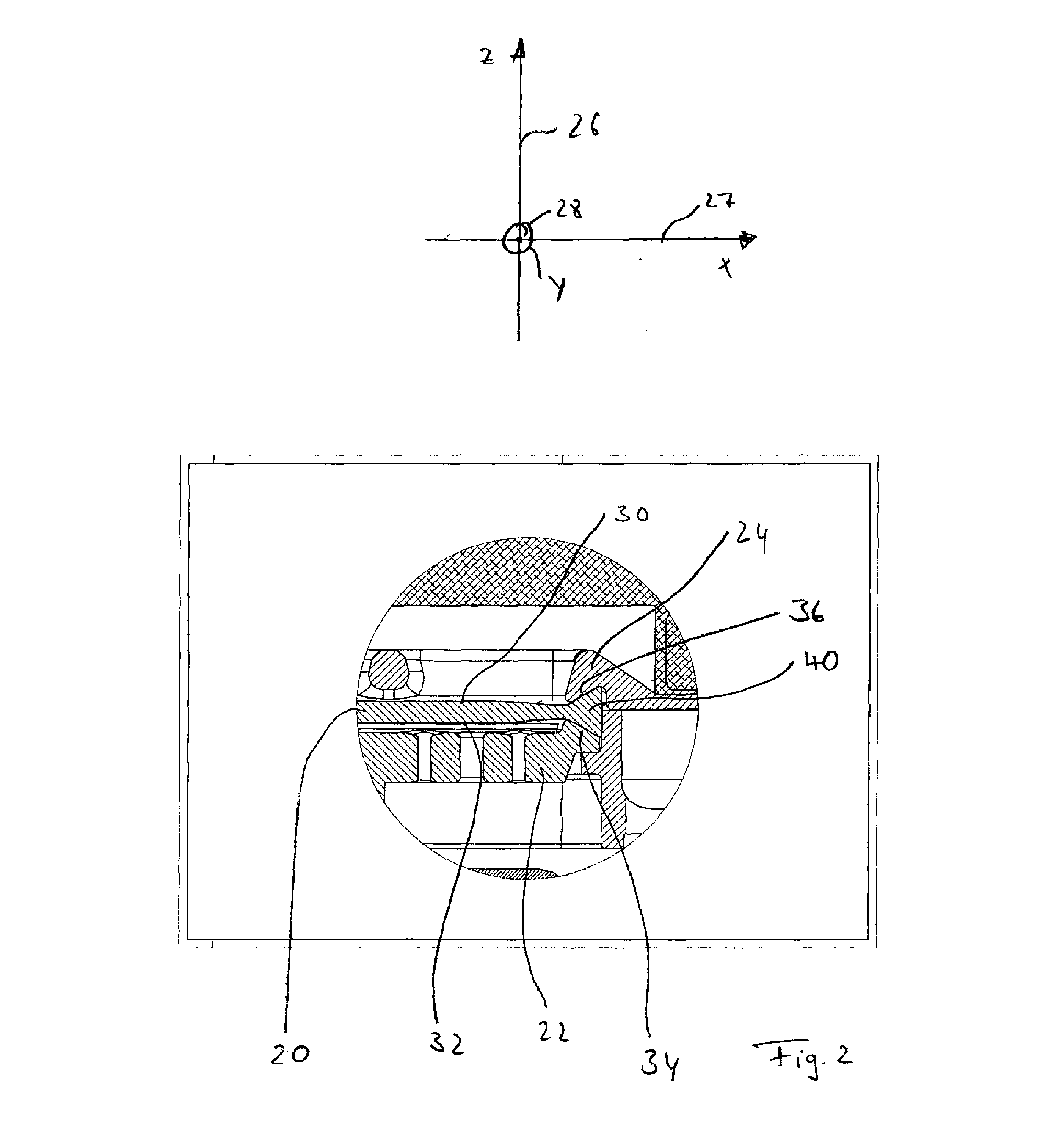
[0013]According to another feature of the invention, the diaphragm has an annular bead, which projects beyond at least one surface of the diaphragm, and the component facing this surface has an annular
oblique plane, the highest point of which is radially on the inside and by means of which the annular bead is clamped. The advantage of this development is the fact that it is a simple matter to produce a radial pretension in the diaphragm with the aid of a bead, which is clamped by means of an
oblique plane.
[0014]According to another feature of the invention, the diaphragm has an annular bead, which projects beyond both surfaces of the diaphragm, and the components facing the surfaces each have an annular
oblique plane, the highest point of which is radially on the inside and by means of which the annular bead is clamped. An advantage of this development is that it is of no account, during the production of the hydromount, in what orientation the diaphragm is laid and clamped between the two components. There can thus be
no production errors. Another advantage of this feature is that a sufficiently large pretension arises in the diaphragm, even with a small pressing displacement of the two components in the axial direction of the hydromount.
[0015]According to another feature of the invention, the angle of the oblique plane is between 30° and 60°. An advantage of this development is that, on the one hand, only small forces have to be applied in order to produce a radial pretension in the diaphragm and, on the other hand, a sufficiently large radial pretension is built up in the diaphragm for a given pretensioning displacement between the two components.
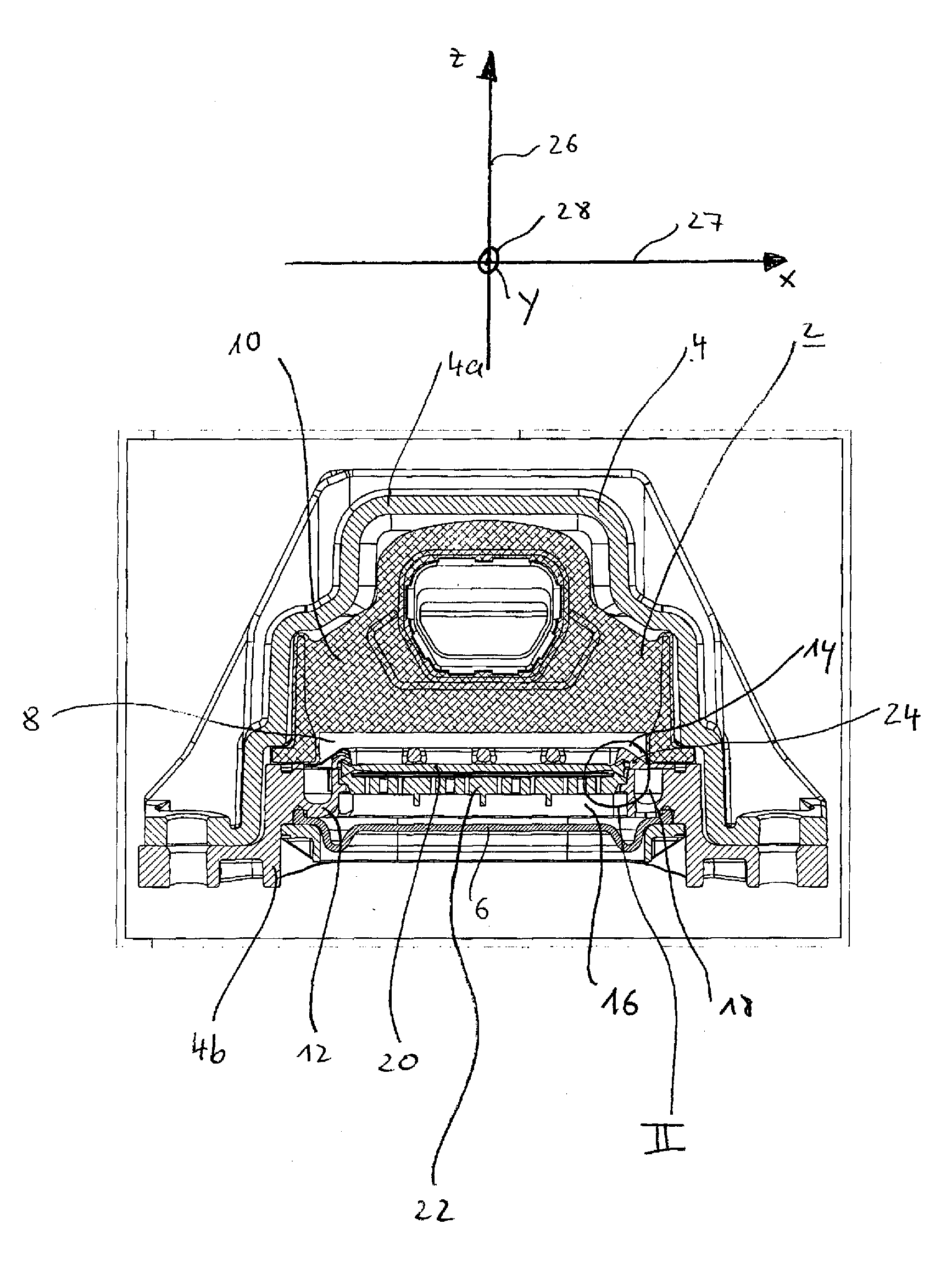
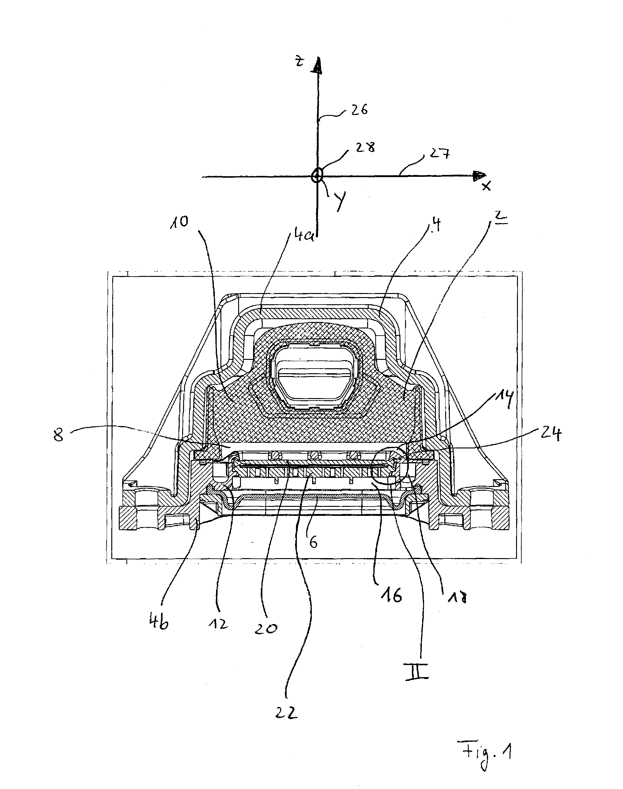
[0016]According to another feature of the invention, the diaphragm is of cup-shaped design with an annular wall which is slotted into an annular groove in the first component, and the first component has a cup-shaped recess which is surrounded by the groove and into which the second component engages in the manner of a cover by means of an annular projection and thereby radially pretensions the diaphragm. An advantage of this feature is that a defined radial pretension can be set in the diaphragm by way of the height of the projection as shown in the drawings and explained hereinafter with respect thereto.

