
Mounting structure for attitude instrument of pesticide spraying unmanned aerial vehicle

A technology of installation structure and aircraft attitude, which is applied to aircraft parts, mechanical equipment, transportation and packaging, etc., can solve the problems affecting the reliability of the attitude instrument, difficult operation by the operator, and loose attitude instrument, so as to achieve easy processing, assembly, The effect of low production cost and reduced impact

Inactive Publication Date: 2018-05-15
刘福珍
View PDF4 Cites 0 Cited by
  • Summary
  • Abstract
  • Description
  • Claims
  • Application Information

AI Technical Summary

Problems solved by technology

Because the unmanned pesticide spraying machine will be affected by wind resistance, airflow and other factors during the flight, it will inevitably produce vibration and turbulence, and this vibration and turbulence will be directly transmitted to the attitude instrument through the bracket, which will affect the reliability of the attitude instrument at least, making the It is difficult for the operator to operate accurately, and it will cause the attitude indicator to loosen or be damaged

Method used


Image

  • Mounting structure for attitude instrument of pesticide spraying unmanned aerial vehicle

Examples


Embodiment Construction

[0011] Below in conjunction with accompanying drawing and embodiment the present invention will be further described:

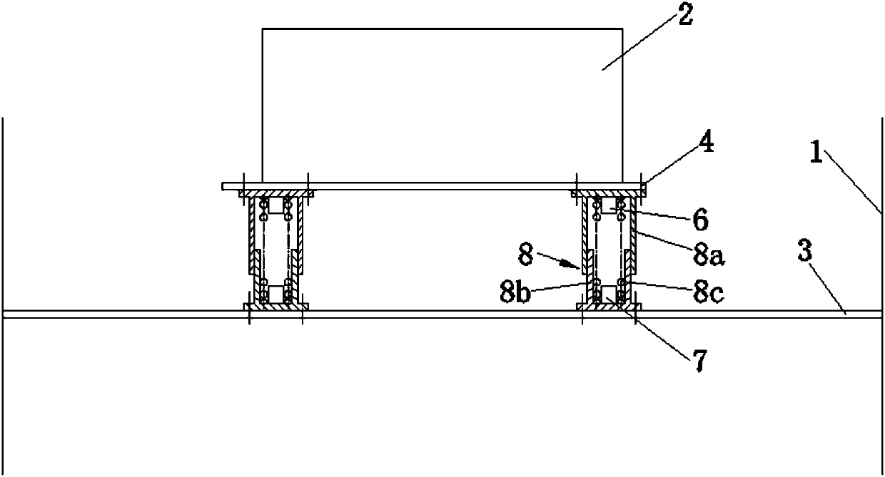
[0012] Such as figure 1 As shown, an attitude instrument 2 and a bulkhead 3 are arranged in the main engine compartment 1, and the bulkhead 3 is fixed with the main engine compartment 1. The attitude meter 2 is located above the partition 3, and has a positioning plate 4 at the bottom of the attitude meter 2. The positioning plate 4 is fixedly connected with the attitude meter 2. The positioning plate 4 is rectangular and parallel to the partition 3. Between positioning plate 4 and dividing plate 3, be provided with four shock absorbers 8 distributed by rectangle, four corners of four shock absorbers 8 corresponding positioning plate 4, make the bottom of positioning plate 4 near the four corners by the shock absorber The vibrator 8 is supported on the partition plate 3 .

[0013] Such as figure 1 As shown, the shock absorber 8 includes an upper guide cyli...


PUM


Abstract

The invention discloses a mounting structure for an attitude instrument of a pesticide spraying unmanned aerial vehicle (UAV). The mounting structure for the attitude instrument of the pesticide spraying UAV comprises a main UAV cabin and the attitude instrument, wherein a partition plate is arranged in the main UAV cabin; a position-fixing plate is arranged at the bottom of the attitude instrument; the position-fixing plate is rectangular and parallel to the partition plate; the parts, near the four corners, of the bottom of the position-fixing plate are supported on the partition plate by shock absorbers; the shock absorbers comprise upper guide cylinders, lower guide cylinders and springs; the top ends of the upper guide cylinders are fixed to the position-fixing plate; the upper ends of the lower guide cylinders are sleeved on the lower ends of the upper guide cylinders; the lower guide cylinders are in sliding cooperation with the upper guide cylinders; the lower ends of the lowerguide cylinders are fixed to the partition plate; each spring is arranged in the enclosed space formed by the corresponding upper guide cylinder and the corresponding lower guide cylinder; a gap is arranged between each spring and the inner side wall of the corresponding lower guide cylinder; the upper end of each spring abuts against the inner top wall of the corresponding upper guide cylinder;and the lower end of each spring abuts against the inner bottom wall of the corresponding lower guide cylinder. The mounting structure for the attitude instrument of the pesticide spraying UAV supports the attitude instrument by virtue of the four shock absorbers distributed in a rectangular manner, so as to not only ensure the firmness of the mounting of the attitude instrument, but also effectively reduce the influence of flying vibration on the attitude instrument, thereby ensuring the reliability and long service life of the attitude instrument.

Description

technical field [0001] The invention belongs to the technical field of agricultural machinery, and in particular relates to an attitude meter installation structure on a pesticide spraying machine. Background technique [0002] At present, the UAV that sprays pesticides automatically generally includes a main engine cabin, a cantilever and a power cabin, and the opening on the top of the main engine cabin is sealed by the main engine cabin cover. The attitude indicator is an important instrument on the unmanned pesticide spraying machine, which shows the attitude of the unmanned pesticide spraying machine relative to the horizon. Through the attitude indicator, the operator on the ground can judge the attitude of the pesticide unmanned sprayer as being left-right, upward or downward. The existing attitude indicator is usually installed in the main engine compartment by a bracket made separately, and the installation method of the attitude indicator is a hard connection. Be...

Claims


Application Information

Patent Timeline
IPC IPC(8): B64D47/00F16F15/02F16F15/04
CPCB64D47/00F16F15/022F16F15/04
Inventor 刘博文刘福珍
Owner 刘福珍
Learn More