Crankshaft bearing of compressor and compressor

A technology for crankshaft bearings and compressors, applied in the field of compressors, can solve the problems of reduced crankshaft rotation stability, bearing wear, etc., and achieve the effects of preventing interference collision and electromagnetic noise, preventing air gap reduction, and reducing wear and tear.

Pending Publication Date: 2019-01-11
ZHUHAI GREE REFRIGERATION TECH CENT OF ENERGY SAVING & ENVIRONMENTAL PROTECTION
View PDF0 Cites 0 Cited by
  • Summary
  • Abstract
  • Description
  • Claims
  • Application Information

AI Technical Summary

Problems solved by technology

[0006] Therefore, the technical problem to be solved by the present invention is to overcome the high-speed rotation of the compressor crankshaft under the constraint of the bearing in the prior art. The unbalanced force generated by the rotor assembly causes the long axis of the crankshaft to bend due to a certain disturbance, resulting in stable rotation of the crankshaft. Sexual decline, easy to wear defects with bearings, so as to provide a compressor crankshaft bearing and compressor

Method used


Image

  • Crankshaft bearing of compressor and compressor
  • Crankshaft bearing of compressor and compressor
  • Crankshaft bearing of compressor and compressor

Examples


Embodiment Construction

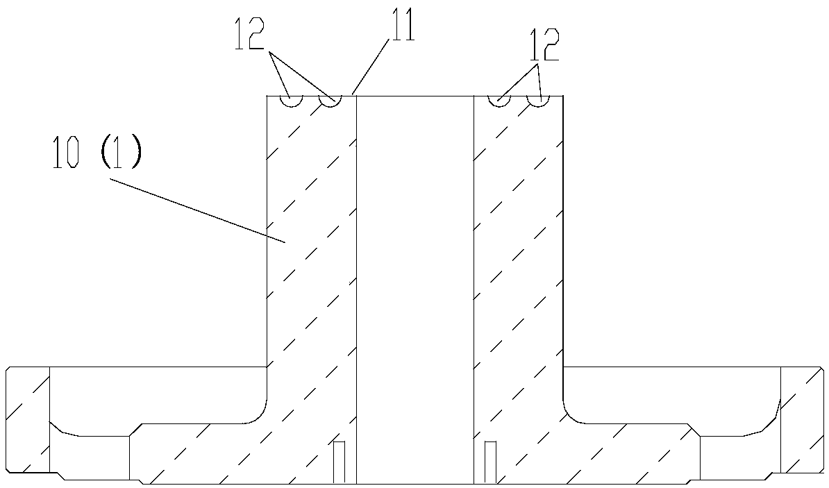
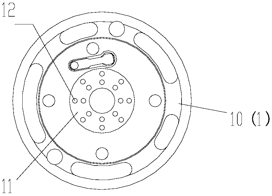
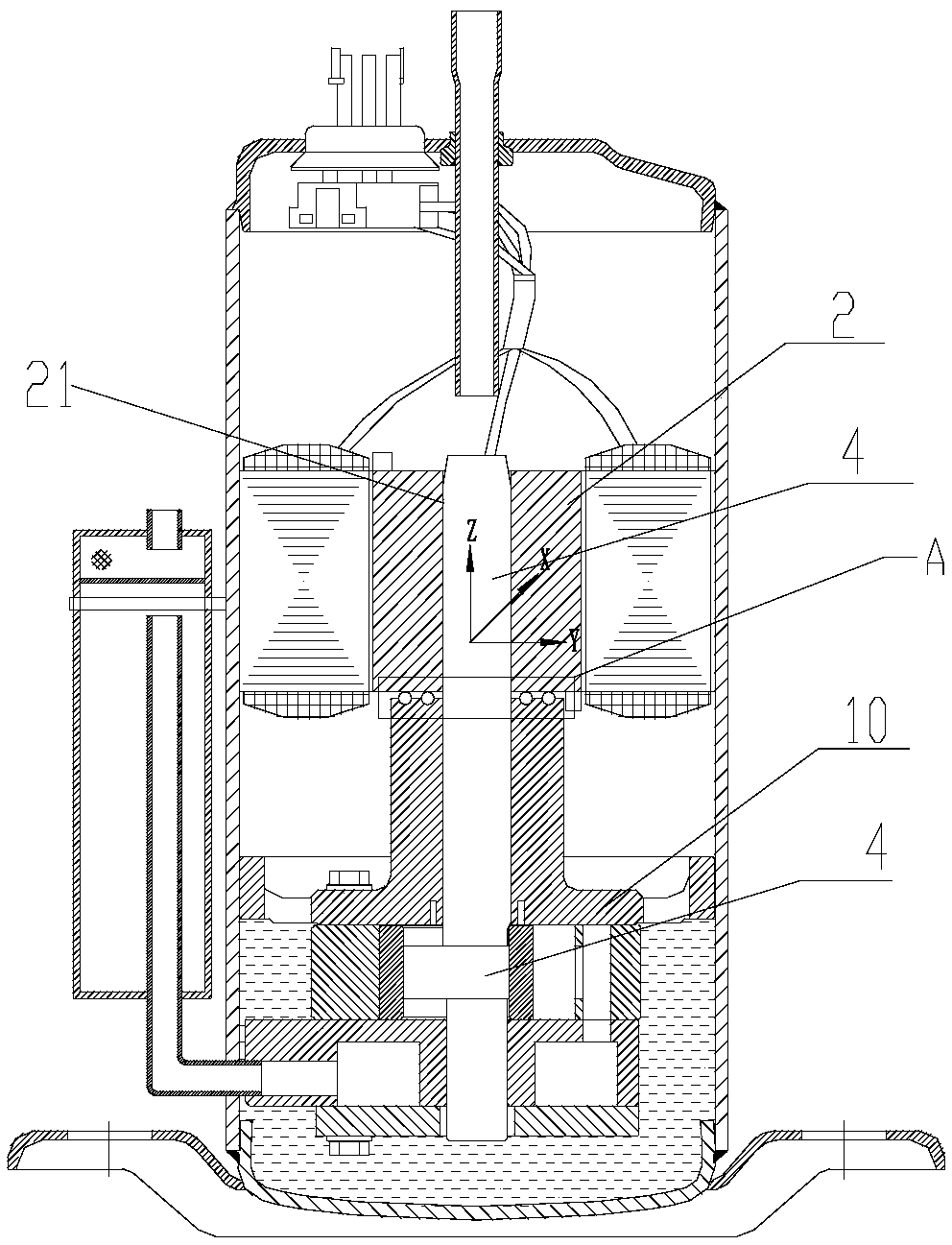
[0034] Such as Figure 1-4 As shown, the present invention provides a crankshaft bearing of a compressor, which includes:

[0035] Bearing body 1, the upper end surface of the bearing body 1 is located below the rotor assembly 2 of the compressor, and a groove 12 is provided on the upper end surface 11 of the bearing body 1, and a rolling body is arranged in the groove 12 3. The rolling body 3 can be in contact with the lower end surface of the rotor assembly 2 so as to support the rotor assembly 2 through the rolling body 3 .

[0036] In the present invention, grooves are provided on the upper end surface of the bearing body, and rolling elements are placed in the grooves, so that the rolling elements are in contact with the lower end surface of the rotor assembly, so that the rotor assembly can be supported by the rolling elements and can be rotated and compressed. When the machine is working, the rotor assembly and the crankshaft rotate at high speed at the same time, and ...


PUM


Abstract

The invention provides a crankshaft bearing of a compressor and the compressor. The crankshaft bearing of the compressor comprises a bearing body (1). The upper end face of the bearing body (1) is located below a rotor assembly (2) of the compressor and is further provided with grooves (12). A rolling body (3) is arranged in each groove (12) and can be connected with the lower end face of the rotor assembly (2) so as to support the rotor assembly (2) through the rolling bodies (3). Through the crankshaft bearing, deflection of a long shaft of a crankshaft can be limited, the long shaft of thecrankshaft cannot be bent, the stability of crankshaft rotating can be improved, and wear between the crankshaft and the bearing is effectively avoided and reduced; and an air gap of a stator and rotor assembly can be prevented from being reduced, and the situations of interference colliding, electromagnetic noise and the like are avoided.

Description

technical field [0001] The invention belongs to the technical field of compressors, and in particular relates to a crankshaft bearing of a compressor and the compressor. Background technique [0002] The structure design of the existing rotary compressor, the rotor assembly is provided with an inner hole, which is an interference fit with the long axis of the crankshaft, and the upper and lower end surfaces are equipped with balance blocks, which generate centrifugal force with the rotation of the compressor, to balance the eccentric circle of the crankshaft and the centrifugal force of the piston force rotation function, thereby reducing compressor vibration and noise. [0003] The crankshaft rotates at high speed under the constraints of the bearings. The unbalanced force generated by the rotor assembly causes the long axis of the crankshaft to bend to a certain extent, and changes the original balance design parameters. The rotation stability of the crankshaft decreases, ...

Claims


Application Information

Patent Timeline
Patent Type & Authority Applications(China)
IPC IPC(8): F16C9/02F04C29/00
CPCF04C29/00F04C2240/50F16C9/02
Inventor 叶晓飞赵旭敏彭慧明
Owner ZHUHAI GREE REFRIGERATION TECH CENT OF ENERGY SAVING & ENVIRONMENTAL PROTECTION
Why Eureka
Try Eureka