Thread stop device and its bar

A technology of automatic stop and slats after menopause, applied in transportation and packaging, embroidery machine mechanism, embroidery machine and other directions, which can solve the problems of slowing down the response speed and high quality.

Inactive Publication Date: 2010-01-20
FRANZ LAESSER DIEPOLDSAU
View PDF7 Cites 0 Cited by
  • Summary
  • Abstract
  • Description
  • Claims
  • Application Information

AI Technical Summary

Problems solved by technology

But it turned out to be a disadvantage that the two-part switch, consisting of the armature and the wire, has a greater mass of the stop piece, which slows down the reaction
The warp breaking self-stop device described in DE4142078 also has the same shortcoming. In this patent, a permanent magnet is arranged on the switch warp stop piece

Method used


Image

  • Thread stop device and its bar
  • Thread stop device and its bar
  • Thread stop device and its bar

Examples


Embodiment Construction

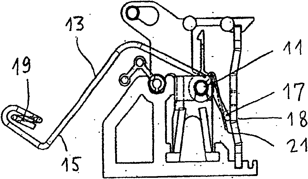
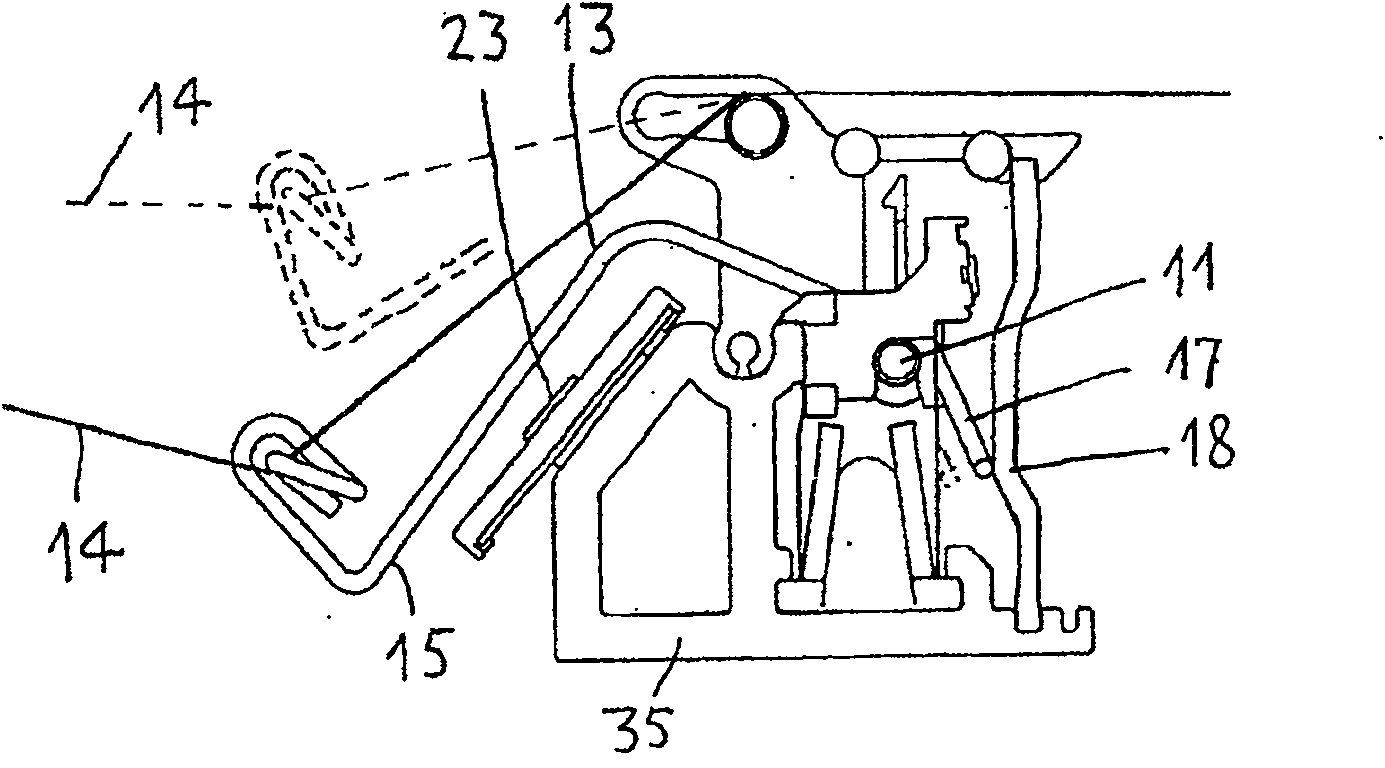
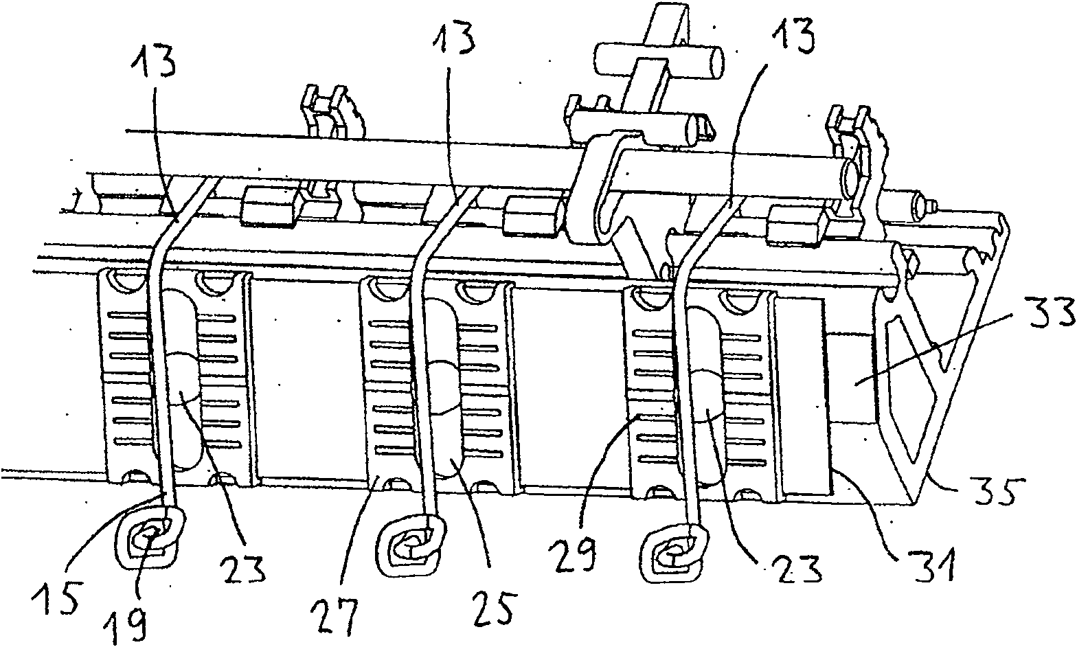
[0021] figure 1 The shown, known prior art warp stop device slat according to EP1098025 has a plurality of warp stop devices for monitoring the thread tension at a plurality of embroidery points such as a shuttle embroidery machine. Each broken warp self-stop device has a switch warp stop piece 13 that can turn around the axle 11, and it is made of wire and has two lever arms 15,17. An eyelet 19 for receiving a face yarn is provided on the lever arm 15 . A spring 21 acts on the lever arm 17, and it will make the switch stop piece 13 enter the position shown in the figure together with the gravity acting on it, where the lever arm 17 contacts the contact rail 18. Thus a fault signal is generated to indicate a broken yarn. Usually, when the embroidery machine is working, the tension in the face yarn 14 will raise the switch warp stop piece, as figure 2 Contact with the contact rail 18 is thus prevented, as indicated by the dotted line in the center.

[0022] figure 2 , 3...


PUM


Abstract

The invention relates to a warp stop motion, comprising a switching warp stop piece (13) which enables rotary support around a shaft (11). The invention is characterized in that the switching warp stop piece falls down to a lower position when yarn is broken to generate a fault signal; a magnet (23) acts on the lever arm (15) with a hole (19) to enable the actions of the warp stop motion not merely rely on gravity acceleration; compared with the prior art, the switching warp stop piece can respond to yarn breaking quickly due to no solid armature; the force acting upon the switching warp stop piece (13) by the magnet (23) can be adjusted according to the requirements of yarn processing by moving the magnet a slot (25).

Description

technical field [0001] The present invention relates to a kind of warp breaking automatic stop device of a rust machine or a quilting machine, which has a switch warp stop piece supported around a shaft and has one or two lever arms and a magnet, one of the lever arms There is an eyelet for receiving the face yarn, and the magnet seeks to make the switch stop piece rotate against the tension of the yarn in order to generate a fault signal when the yarn breaks. Background technique [0002] Warp stop devices have been used on embroidery or quilting machines for decades. Therefore, for example, CH594080 describes a warp stop device, in which the warp yarn to be monitored acts on a switch warp stop piece, which is set up or disconnected according to the warp yarn tension at the time at two different voltages. electrical connection between the rods. During the interval, the work speed of the embroidery or quilting machine has been greatly increased. This brings up some proble...

Claims


Application Information

Patent Timeline
Patent Type & Authority Patents(China)
IPC IPC(8): D05C11/14B65H63/028D05C11/08
CPCD05C11/14
Inventor F·拉泽
Owner FRANZ LAESSER DIEPOLDSAU
Why Eureka
Try Eureka