Top mounting can container

a can container and top mounting technology, applied in the field of containers, can solve the problems of limited food volume capacity of the top-mounted container, and achieve the effects of increasing the stackable strength of the container, increasing strength, and increasing food volume capacity

Inactive Publication Date: 2013-03-07
SNACKTOPS
View PDF12 Cites 8 Cited by
  • Summary
  • Abstract
  • Description
  • Claims
  • Application Information

AI Technical Summary

Benefits of technology

[0014]The vertical dimension of the cavity may vary from a low, for example about a half an inch when the container is configured to hold a cookie, to a medium, for example about one and a half inches when the container is configured to hold crackers or a doughnut or high, for example up to or more than four inches when the container is configured to hold ice cream or french fries. As one skilled in the art will appreciate, any desired dimension of the container may be utilized as desired for the particular application. The outer horizontal dimension of the container may be of a width less than, equal to, or greater than the diameter of the outside dimension of the can. However the preferred embodiment is when the container diameter is equal to the horizontal diameter of the outside of the can. Strength ribs may be utilized in one or more embodiments of the invention to increase the stackable strength of the container. These ribs may include vertically thicker beams on the inside or outside of the container, or alternatively or in combination, may also make use of thicker walls on the container to increase strength. As specified herein, a larger food volume capacity may be provided in the case of right side up containers as compared to upside down containers. This becomes evident when looking at right side up and upside down containers that attach to the same horizontal diameter on the top of the cup or can. Upside down containers are those for example which clip on to the top of yogurt cups that start in an upside down position and then must be removed and flipped over in order to access the contents of the container. Upside down containers have a limited food volume capacity due to the fact that they utilize vertical sidewalls that slant inward (necessary for stacking containers) as they proceed upward toward the bottom of the container (when placed upside down on a yogurt cup). Right side up containers do not need to be flipped to access the contents and have vertical sidewalls that slant outward as they proceed upward toward the rim of the container. The inwardly slanting vertical sidewalls of upside down containers limit the food volume capacity of the top container, while the outwardly slanting vertical sidewalls of right side up containers provide for increased food volume capacity of the top container.
[0021]Embodiments of the invention allow for one-handed transportation and simultaneous access of the contents of the container and can after momentarily removing and reattaching the container to the can. Although, as specified here within, a clip-on system of engagement of the upper container to the bottom can mount element may be utilized, which allows the user to remove or reattach the container as a separate vessel from the can mount element as desired. Various embodiments allow for ease of carrying and drinking / eating coffee, soda, cookies, snacks, etc., in malls, public zoos, amusement parks, sports stadiums or in any other venue. For example, this allows a parent in an amusement park to carry food and beverages at the same time with one hand, while providing one hand free to hold the hand of a child for safety. In addition, embodiments of the invention simplify eating and drinking by combining these processes into one container and can, which is significantly more convenient in amusement parks or stadiums having seats, for example, which provide a single beverage holder per seat.

Problems solved by technology

Upside down containers have a limited food volume capacity due to the fact that they utilize vertical sidewalls that slant inward (necessary for stacking containers) as they proceed upward toward the bottom of the container (when placed upside down on a yogurt cup).

Method used


Image

  • Top mounting can container
  • Top mounting can container
  • Top mounting can container

Examples


Embodiment Construction

[0032]A top mounting can container will now be described. In the following exemplary description numerous specific details are set forth in order to provide a more thorough understanding of embodiments of the invention. It will be apparent, however, to an artisan of ordinary skill that the present invention may be practiced without incorporating all aspects of the specific details described herein. In other instances, specific features, quantities, or measurements well known to those of ordinary skill in the art have not been described in detail so as not to obscure the invention. Readers should note that although examples of the invention are set forth herein, the claims, and the full scope of any equivalents, are what define the metes and bounds of the invention.

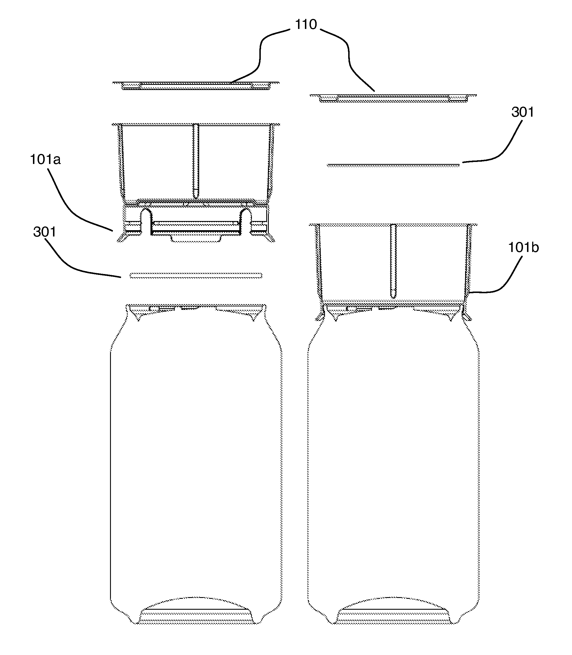
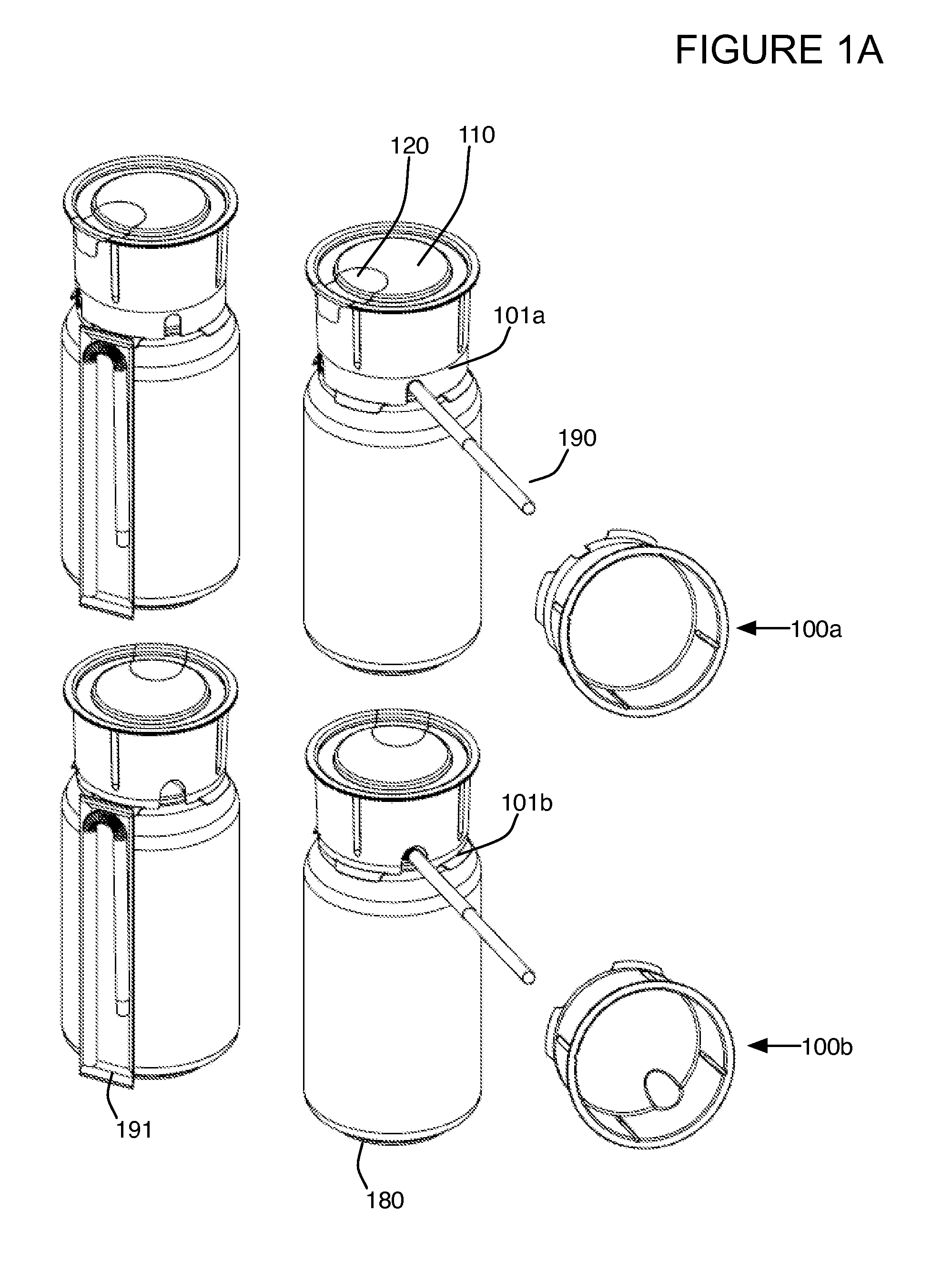
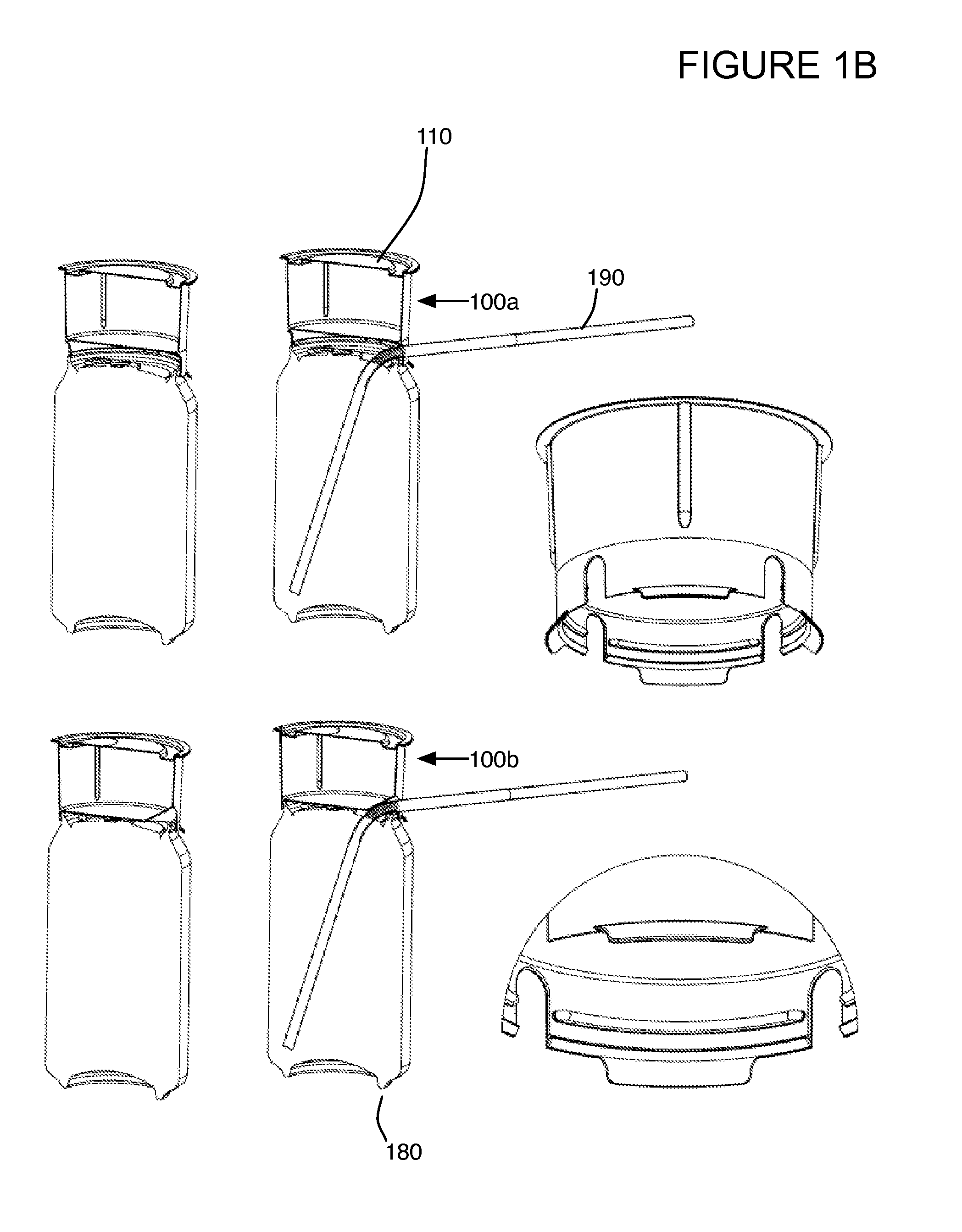
[0033]FIG. 1A illustrates a perspective view of a first embodiment of top mounting can container 100a shown in the upper right portion of the figure and rotated to show the volume within the container. Container 100a is al...


PUM


Abstract

Top mounting can container that couples with a can. One or more embodiment enables simultaneous access to both the contents of the can and contents of the container. A half circle cut-out in the lid provides for spill free snacking from an independent vessel. Various configurations enable the inclusion of fresh food, eating and drinking from a straw if desired while standing and walking and access of solid or liquid in the container and can. Coupling elements that couple the top mounting can container to the can, may utilize any type of easily removable or semi-removable technology. Simplifies eating and drinking from one container and can in a theater or stadium having seats for example that provide one beverage holder per seat. Provides one free hand to hold a child's hand for safety while in stadiums and amusement parks.

Description

[0001]This application is a continuation of U.S. Utility patent application Ser. No. 13 / 303,080 filed 22 Nov. 2011, which is a continuation-in-part of U.S. Utility patent application Ser. No. 13 / 226,346 filed 6 Sep. 2011, the specifications of which are hereby incorporated herein by reference.BACKGROUND OF THE INVENTION[0002]1. Field of the Invention[0003]One or more embodiments of the invention are related to the field of containers. More particularly, but not by way of limitation, one or more embodiments of the invention provides for a top mounting can container that enables for example one handed carrying of the can and container and / or simultaneous access, through a straw if desired, of the contents of the can and container after momentarily removing and reattaching the top mounting container to the can. An alternative configuration is where the container is removed from the can and utilized as a separate unit or vessel. When a pull tab removes a piece of the lid in a half-circl...

Claims


Application Information

Patent Timeline
Patent Type & Authority Applications(United States)
IPC IPC(8): B65D21/02B65D25/00B65D25/14B65D43/00B65D81/38
CPCB65D81/3205B65D21/0237
Inventor BUCK, RONALD MARK
Owner SNACKTOPS
Why Eureka
Try Eureka