Network control apparatus and method with table mapping engine
What is AI technical title?
AI technical title is built by PatSnap AI team. It summarizes the technical point description of the patent document.
a network control and table mapping technology, applied in data switching networks, fault response, instruments, etc., can solve the problems of increasing process difficulty, l2 domains cannot scale to large sizes, and retaining tenant isolation greatly complicating mobility
Active Publication Date: 2013-03-07
NICIRA
View PDF5 Cites 61 Cited by
Summary
Abstract
Description
Claims
Application Information
AI Technical Summary
This helps you quickly interpret patents by identifying the three key elements:
Problems solved by technology
Method used
Benefits of technology
Benefits of technology
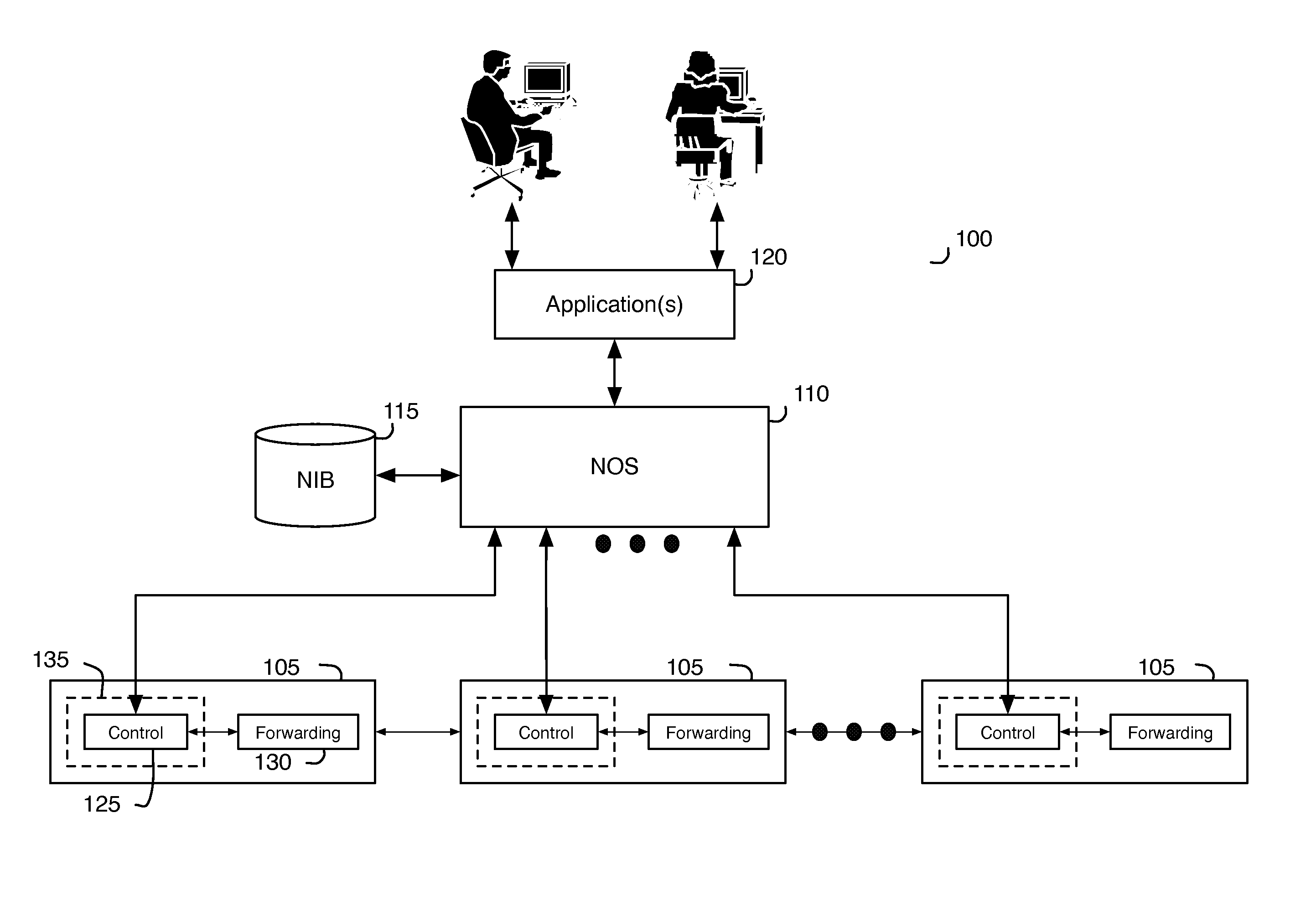
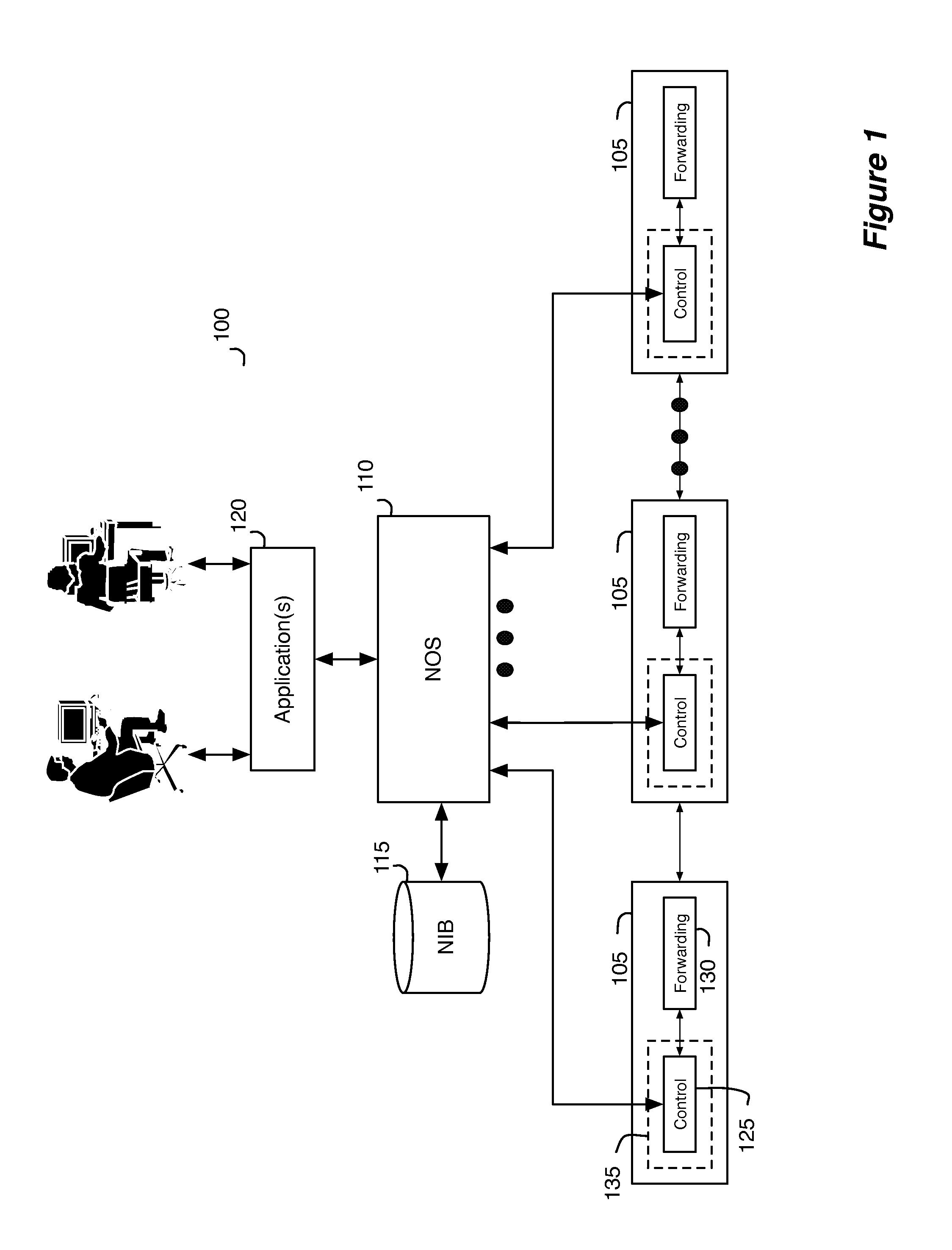
[0005]Some embodiments of the invention provide a system that allows several different logical data path sets to be specified for several different users through one or more shared network infrastructure switching elements (referred to as “switching elements” below). In some embodiments, the system includes a set of software tools that allows the system to accept logical data path sets from users and to configure the switchi
Problems solved by technology
This process is of increased difficulty where the network switching elements are shared across multiple users.
Three of the many challenges of large networks (including datacenters and the enterprise) are scalability, mobility, and multi-tenancy and often the approaches taken to address one hamper the other.
For in
Method used
Image
Click on the blue label to locate the original text in one second.
Reading with bidirectional positioning of images and text.
Examples
Embodiment Construction
[0083]In the following detailed description of the invention, numerous details, examples, and embodiments of the invention are set forth and described. However, it will be clear and apparent to one skilled in the art that the invention is not limited to the embodiments set forth and that the invention may be practiced without some of the specific details and examples discussed.
[0084]Some embodiments of the invention provide a method that allows several different logical data path sets to be specified for several different users through one or more shared switching elements without allowing the different users to control or even view each other's switching logic. In some embodiments, the method provides a set of software tools that allows the system to accept logical data path sets from users and to configure the switching elements to implement these logical data path sets. These software tools allow the method to virtualize control of the shared switching elements and the network th...
PUM
Abstract
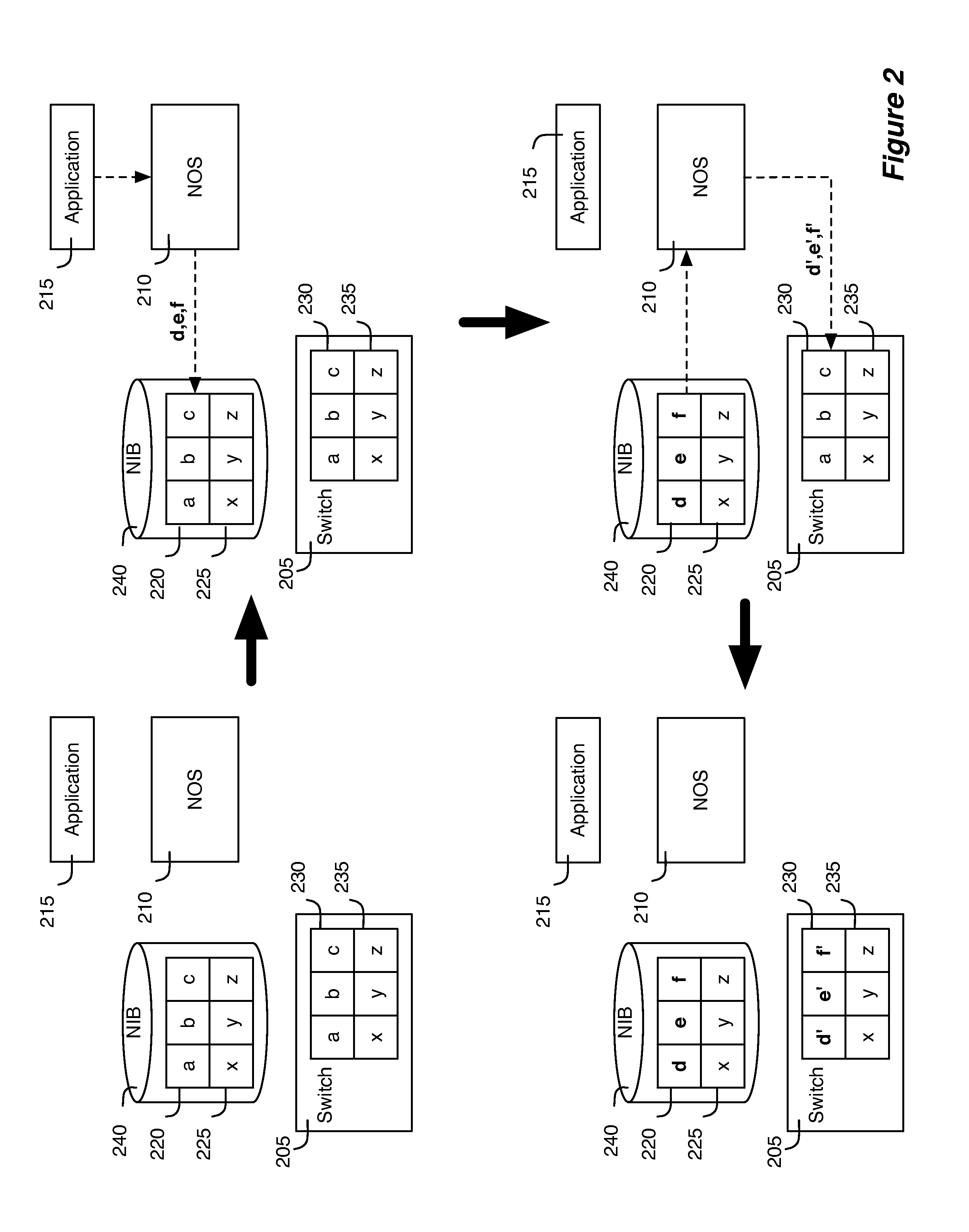
Some embodiments provide a controller for managing a plurality of managed switching elements that forward data through a network. The controller comprising a first set of tables for storing input logical control plane data, and a second set of tables for storing output logical forwarding plane data. It also includes a table mapping engine for mapping the input logical control plane data in the first set of tables to output logical forwarding plane data in the second set of tables by performing a set of database join operations on the input logical control plane data in the first set of tables. The logical forwarding plane data is subsequently translated into physical forwarding behaviors that direct the forwarding of data by the managed switching elements.
Description
CLAIM OF BENEFIT TO PRIOR APPLICATIONS[0001]This application claims benefit to U.S. Provisional Patent Application 61 / 361,912, filed on Jul. 6, 2010; U.S. Provisional Patent Application 61 / 361,913, filed on Jul. 6, 2010; U.S. Provisional Patent Application 61 / 429,753, filed on Januar 4, 2011; U.S. Provisional Patent Application 61 / 429,754, filed on Jan. 4, 2011; U.S. Provisional Patent Application 61 / 466,453, filed on Mar. 22, 2011; U.S. Provisional Patent Application 61 / 482,205, filed on May 3, 2011; U.S. Provisional Patent Application 61 / 482,615, filed on May 4, 2011; U.S. Provisional Patent Application 61 / 482,616, filed on May 4, 2011; U.S. Provisional Patent Application 61 / 501,743, filed on Jun. 27, 2011; and U.S. Provisional Patent Application 61 / 501,785, filed on Jun. 28, 2011. These provisional applications are incorporated herein by reference.BACKGROUND[0002]Many current enterprises have large and sophisticated networks comprising switches, hubs, routers, servers, workstatio...
Claims
Application Information
Patent Timeline
Application Date:The date an application was filed.
Publication Date:The date a patent or application was officially published.
First Publication Date:The earliest publication date of a patent with the same application number.
Issue Date:Publication date of the patent grant document.
PCT Entry Date:The Entry date of PCT National Phase.
Estimated Expiry Date:The statutory expiry date of a patent right according to the Patent Law, and it is the longest term of protection that the patent right can achieve without the termination of the patent right due to other reasons(Term extension factor has been taken into account ).
Invalid Date:Actual expiry date is based on effective date or publication date of legal transaction data of invalid patent.

