
Connector with lever

a technology of levers and connectors, applied in the direction of connection, electrical apparatus, coupling device connections, etc., can solve the problems of reducing operating efficiency, and achieve the effects of enhancing toggle action, increasing the rotation angle of the lever, and enhancing rigidity of the lock member

Inactive Publication Date: 2013-03-07
MOLEX INC
View PDF8 Cites 10 Cited by
  • Summary
  • Abstract
  • Description
  • Claims
  • Application Information

AI Technical Summary

Benefits of technology

The present invention is a connector with a lever that solves problems with conventional connectors. It eliminates the need for a cover to protect the lock member, makes unlocking easier, increases the rotating angle for a better toggle action, increases rigidity for a stronger click feeling when locked, improves operability, and reduces the size of the housing. The connector with a lever is designed with the opposite ends of a plate-like lock member connected to the housing, eliminating the need for a cover and improving the overall user experience.

Problems solved by technology

Accordingly, a click feeling generated when locking the engaging lever 303 becomes weak and therefore the operator cannot appropriately perceive that the engaging lever 303 is locked, resulting in reduction of the operating efficiency.

Method used


Image

  • Connector with lever
  • Connector with lever
  • Connector with lever

Examples


Embodiment Construction

[0029]The preferred embodiment of the present invention will be described below in detail with reference to the accompanying drawings.

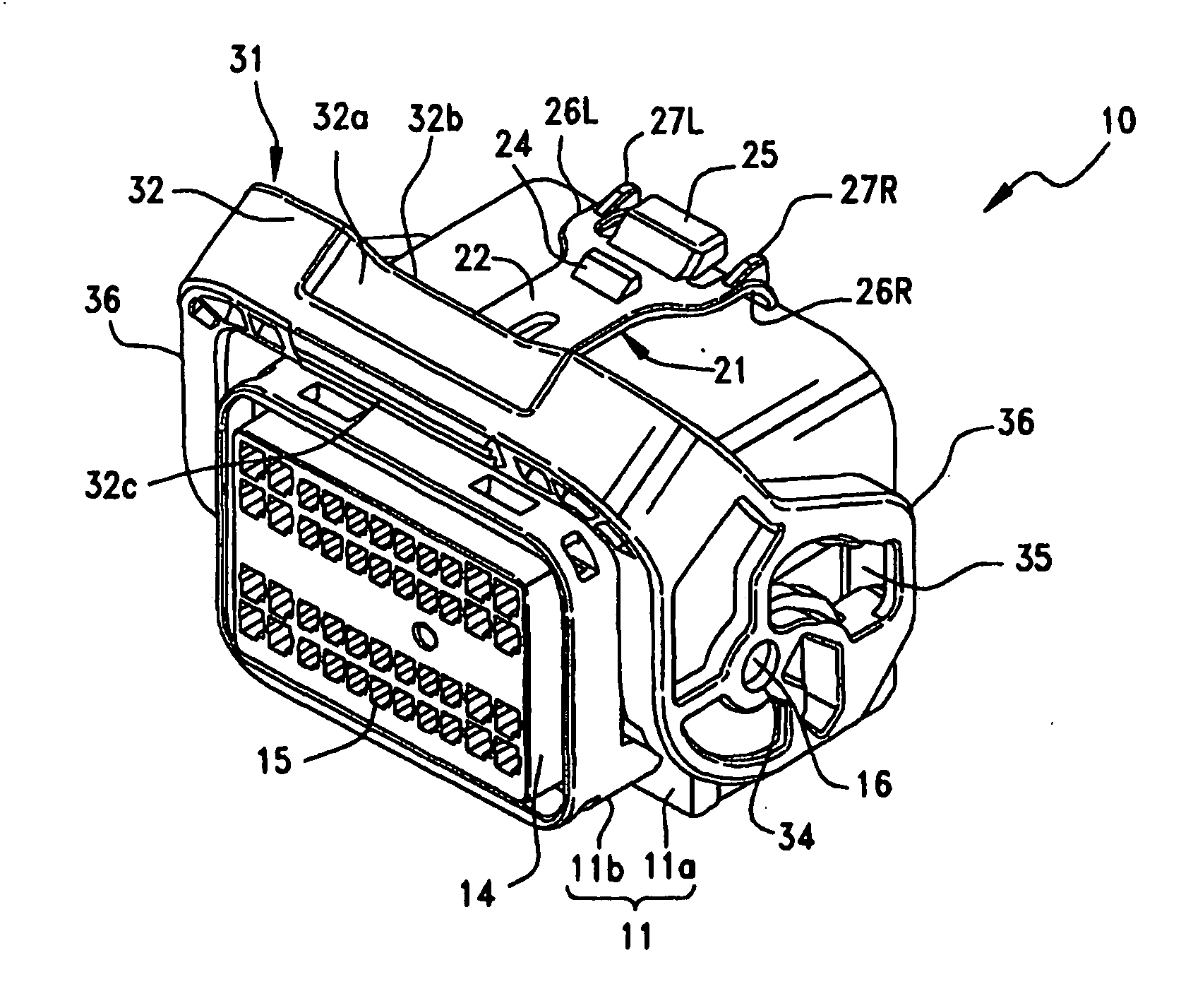
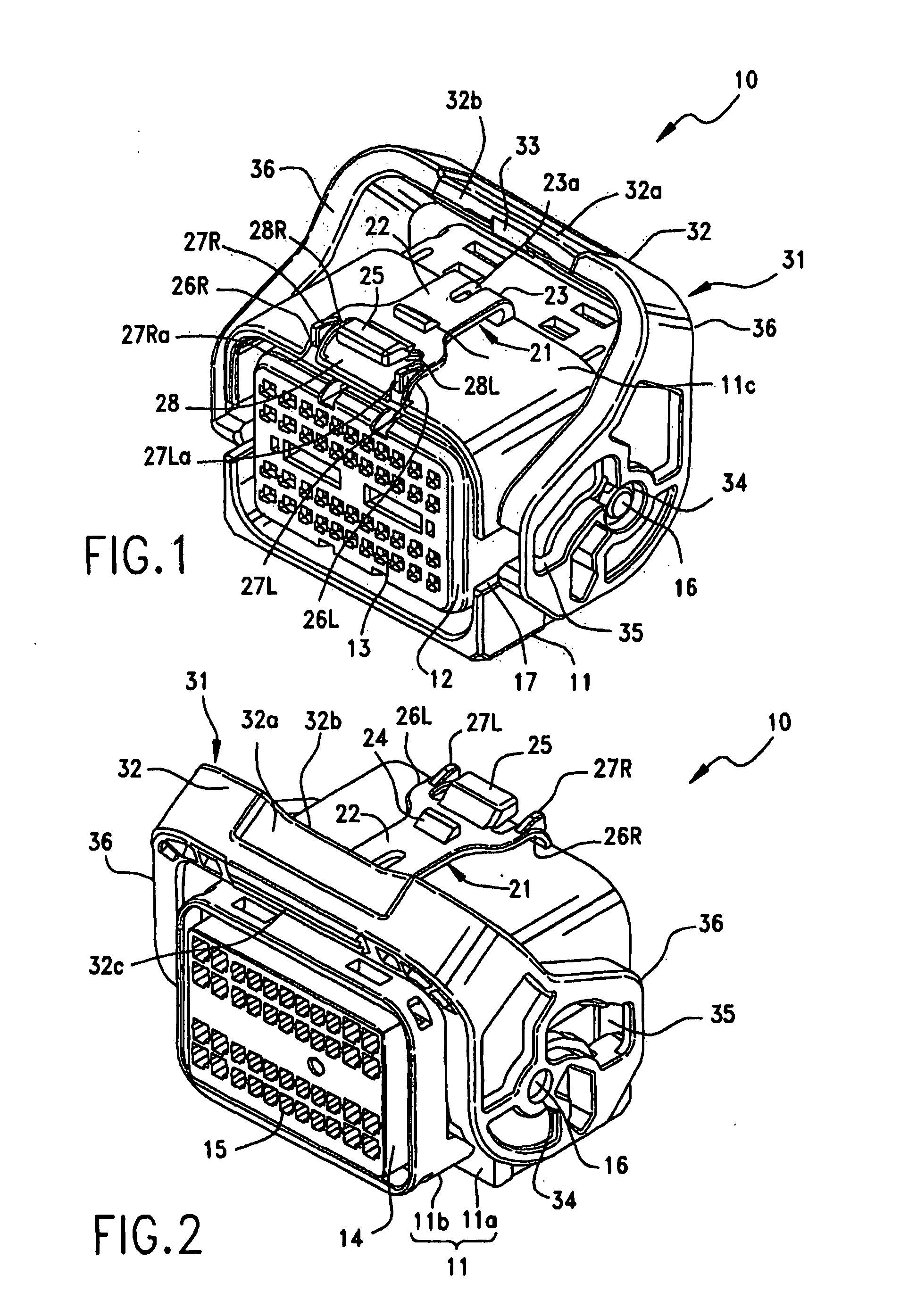
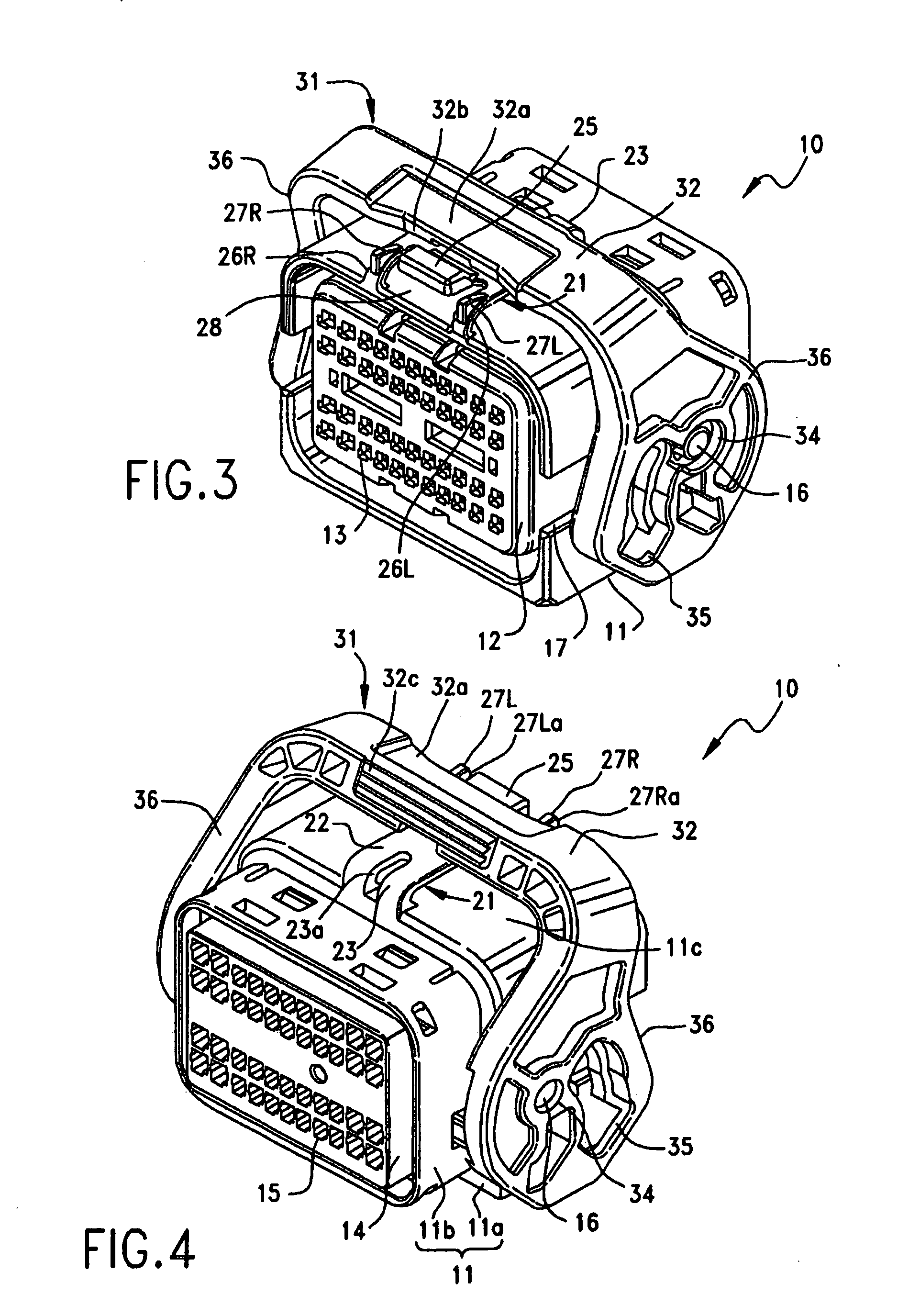
[0030]FIG. 1 is a perspective view of the fitting surface side of a connector according to an embodiment of the present invention, illustrating a state where an engaging lever is in the first position; FIG. 2 is a perspective view of a rear surface side of the connector according to the embodiment of the present invention, illustrating a state where the engaging lever is in the first position; FIG. 3 is a perspective view of the fitting surface side of the connector according to the embodiment of the present invention, illustrating a state where the engaging lever is in the second position; and FIG. 4 is a perspective view of the rear surface side of the connector according to the embodiment of the present invention, illustrating a state where the engaging lever is in the second position.

[0031]In the figures, reference numeral 10 designates a connecto...


PUM


Abstract

A connector is provided with a rotatable toggle lever which is movable between a first position where the connector is fitted to a counterpart connector and a second position in which the connector is secured to the counterpart connector. The connector includes a housing and a lock member for locking the lever at the second position. The lock member has a body portion extending approximately parallel with one wall surface of the housing. The lock member has a locking engaging projection portion for engagement with the lever and, at one end of the body, has a releasing operation portion for releasing the engagement of the projection. A first connection portion connects the other end of the body portion to the one wall surface while second connection portions are arranged on both sides of the releasing operation portion to connect the one end of the body portion to the one wall surface. The lock member further includes cable protective projections projecting from the surfaces of the second connection portions in a direction away from the one wall surface. The lever includes a cross frame portion having a concave portion formed in a position located adjacent the releasing operation portion when the lever is in the second position.

Description

BACKGROUND OF THE INVENTION[0001]1. Field of the Invention[0002]The present invention relates to a connector with a lever.[0003]2. Description of the Related Art[0004]Conventionally, a connector to be fitted in a counterpart connector disposed on a sidewall of a casing accommodating an electronic apparatus such as a control device or the like for various equipment has an engaging lever having an engaging hole, so that the connector is fitted in the counterpart connector with an increased fitting force by turning the engaging lever in a state that the engaging hole is engaged with an engaging projection disposed on the casing (for example, refer to Japanese Patent Application Laid-Open (Kokai) No. 2005-317384).[0005]FIG. 9 is a perspective view illustrating a conventional connector.[0006]In the figure, reference numeral 301 designates a housing of a conventional connector, which is made of an insulating material such as synthetic resin. In a fitting surface of the housing 301, a plur...

Claims


Application Information

Patent Timeline
IPC IPC(8): H01R11/22
CPCH01R13/6272H01R13/62933H01R13/62955H01R13/6295H01R13/62938
Inventor HORI, TAKAYUKI
Owner MOLEX INC
Learn More