
Image stabilization apparatus, image capture apparatus comprising the same, and controlling methods thereof

a technology of image stabilization and image capture, which is applied in the direction of instruments, color television details, television systems, etc., can solve the problems of inability to perform satisfactory image blur correction, lens cannot be moved, and the shake generated by panning operation is generally too large to cancel, so as to suppress the degradation of image quality

Active Publication Date: 2013-03-14
CANON KK
View PDF14 Cites 39 Cited by
  • Summary
  • Abstract
  • Description
  • Claims
  • Application Information

AI Technical Summary

Benefits of technology

The present invention provides an image stabilization apparatus that addresses the issue of the shake compensation lens staying at a maximum driving position, which can cause degraded image quality. The invention also provides a solution for maintaining an anti-shake capacity while addressing the deviation of the shake compensation lens from the center of the optical axis. The invention also includes an image capture apparatus comprising this image stabilization apparatus and control methods for it.

Problems solved by technology

This is because a shake generated by the panning operation is generally too large to cancel even if the shake compensation lens is moved by a maximum amount.
At the end of the panning operation, the shake compensation lens cannot be moved in this direction any more, and no satisfactory image blur correction can be performed.
However, if panning control acts, though the user does not actually perform panning shooting, the anti-shake capacity becomes poor.
However, the method disclosed in Japanese Patent Laid-Open No. 2006-201723 neither suppresses a phenomenon in which the shake compensation lens stays at the maximum driving position, nor suppresses degradation of the image quality caused by deviation of the shake compensation lens from the center of the optical axis of the imaging optical system while providing an anti-shake capacity necessary for the situation.

Method used


Image

  • Image stabilization apparatus, image capture apparatus comprising the same, and controlling methods thereof
  • Image stabilization apparatus, image capture apparatus comprising the same, and controlling methods thereof
  • Image stabilization apparatus, image capture apparatus comprising the same, and controlling methods thereof

Examples


Embodiment Construction

[0028]Exemplary embodiments of the present invention will now be described in detail in accordance with the accompanying drawings.

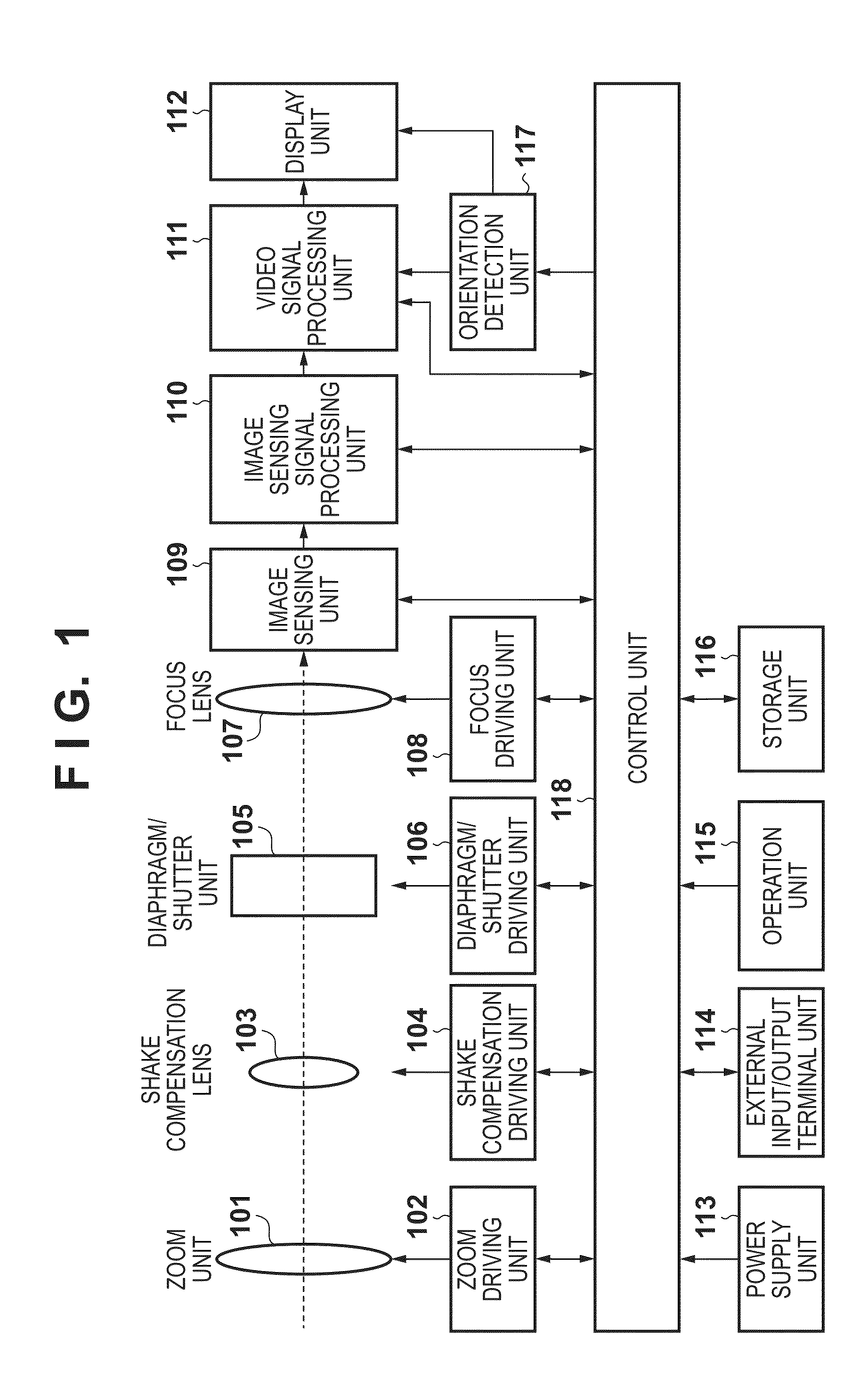
[0029]FIG. 1 is a block diagram exemplifying the functional arrangement of an image capture apparatus including an image stabilization apparatus according to an embodiment of the present invention. In the embodiment, an image capture apparatus 100 is a digital still camera, but may have a moving image shooting function.

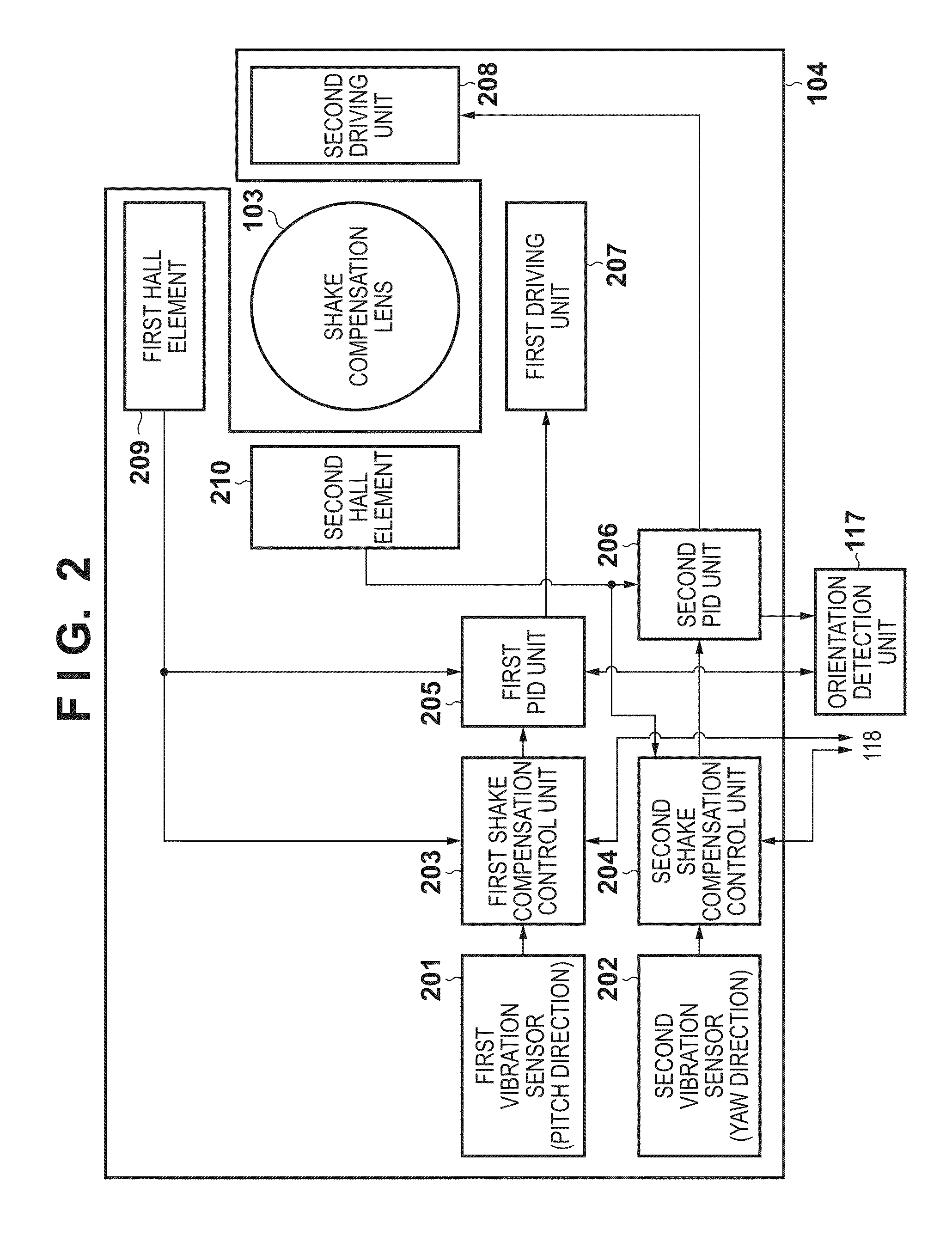
[0030]A zoom unit 101 is part of a photographing lens which forms an imaging optical system. The zoom unit 101 includes a zoom lens for changing the lens magnification. A zoom driving unit 102 controls driving of the zoom unit 101 under the control of a control unit 118. A shake compensation lens 103 is movable in a direction perpendicular to the optical axis of the photographing lens. A shake compensation driving unit 104 controls driving of the shake compensation lens 103.

[0031]A diaphragm / shutter unit 105 is a mechanical shutter having t...


PUM


Abstract

When a shutter speed in shooting by an image capture apparatus using an image stabilization apparatus is higher than a first predetermined value and lower than a second predetermined value which is higher than the first predetermined value, a shake compensation driving unit sets the movable range of a shake compensation lens to be wider than that when it is lower than the first predetermined value or higher than the second predetermined value. While providing an anti-shake capacity necessary for the situation, a phenomenon in which the shake compensation lens stays at a maximum driving position and degradation of the image quality caused by deviation of the shake compensation lens from the center of the optical axis can be suppressed.

Description

BACKGROUND OF THE INVENTION[0001]1. Field of the Invention[0002]The present invention relates to an image stabilization apparatus, an image capture apparatus comprising an image stabilization apparatus, and control methods thereof and, more particularly, to an image stabilization apparatus having an image blur correcting function, an image capture apparatus comprising such an image stabilization apparatus, and control methods thereof.[0003]2. Description of the Related Art[0004]There has conventionally been known an image capture apparatus, including an image stabilization apparatus which detects a shake of the image capture apparatus and drives a movable member (shake compensation lens and its holding member) to correct image blur arising from the shake. Shake detection in the image stabilization apparatus often uses an angular velocity sensor. The angular velocity sensor vibrates a vibration member such as a piezoelectric element at a predetermined frequency, and outputs, as angul...

Claims


Application Information

Patent Timeline
Patent Type & Authority Applications(United States)
IPC IPC(8): H04N5/225H04N23/40
CPCH04N5/23258G03B2217/005G03B2205/0015H04N5/23287H04N23/6812H04N23/687
Inventor TAKEUCHI, KENJI
Owner CANON KK
Learn More