Drive tool device having drive handle

a technology of a tool device and a handle, which is applied in the direction of screwdrivers, wrenches, manufacturing tools, etc., can solve the problems of not being the user cannot be solidly and stably or suitably or effectively pivoted or actuated or driven or rotated with the elongated shaft, and the user cannot effectively and effectively pivoted or rotated, etc., to achieve the effect of easy and readily pi

Inactive Publication Date: 2013-03-21
LI YI CHENG
View PDF7 Cites 8 Cited by
  • Summary
  • Abstract
  • Description
  • Claims
  • Application Information

AI Technical Summary

Benefits of technology

[0008]The primary objective of the present invention is to provide a drive tool device including a drive handle member for allowing the drive tool device to be easily and readily pivoted or rotated relative to the work piece or the like with the drive handle member and for allowing the user to easily and readily conduct various fastener actuating or driving operations.

Problems solved by technology

However, the elongated shaft includes a cylindrical and smooth outer appearance or structure or configuration that may not be firmly held or grasped or gripped by the user and that may not be effectively pivoted or actuated or driven or rotated relative to the work piece or the like with the elongated shaft such that the driven element, socket, tool element, tool extension, fastener, or similar articles may not be solidly and stably or suitably or effectively pivoted or actuated or driven or rotated with the elongated shaft by the user.

Method used


Image

  • Drive tool device having drive handle
  • Drive tool device having drive handle
  • Drive tool device having drive handle

Examples


Embodiment Construction

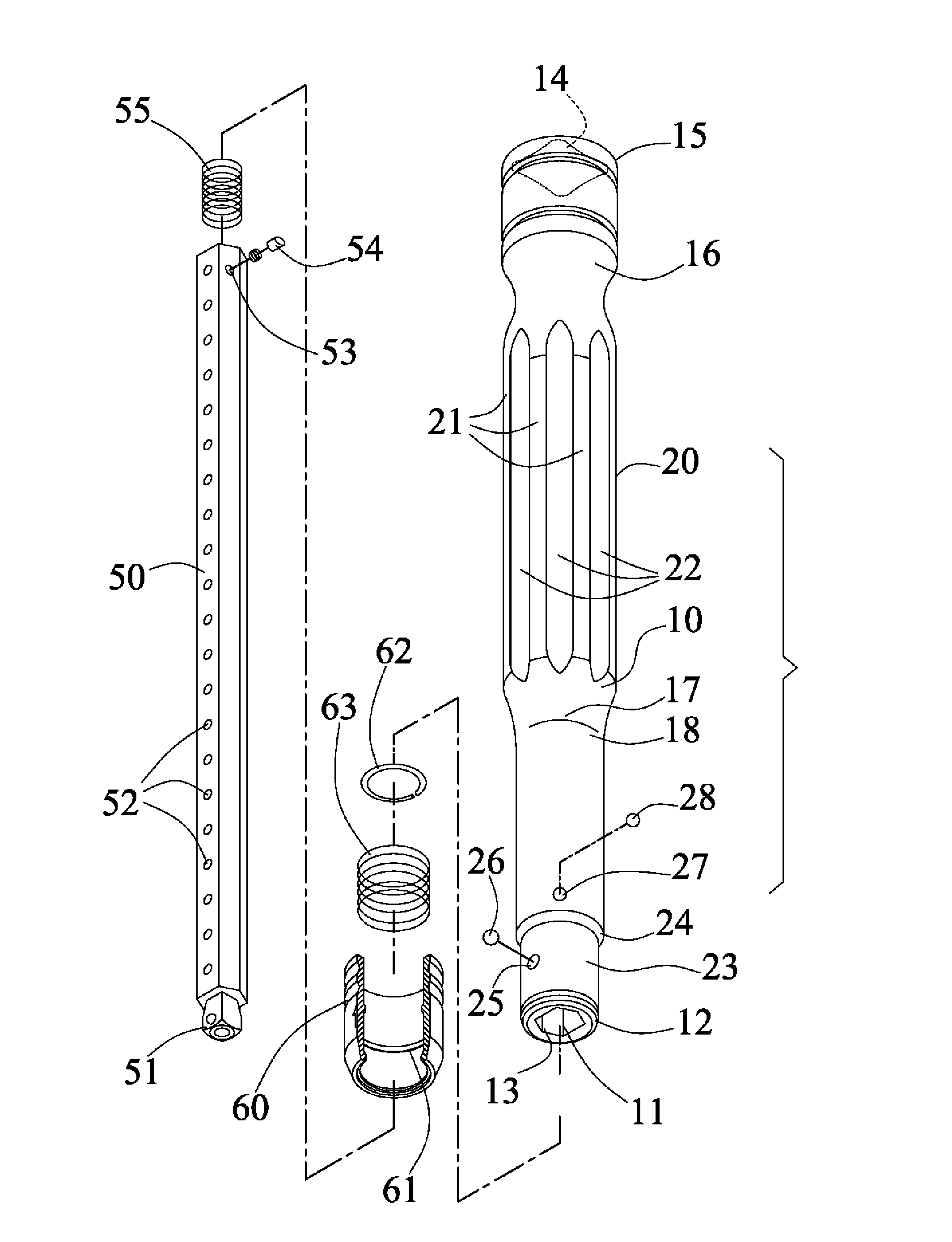
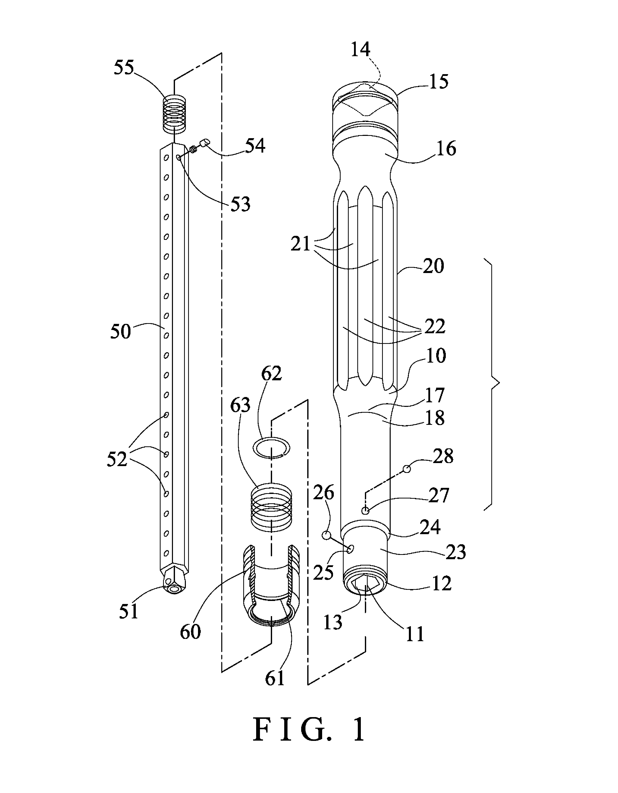
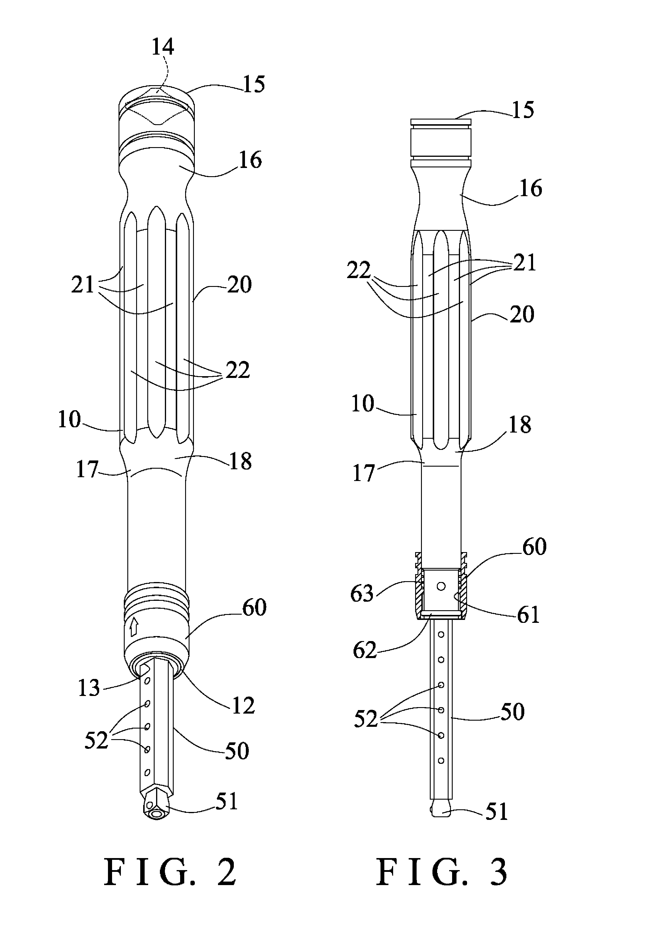
[0030]Referring to the drawings, and initially to FIGS. 1-4, a drive tool device in accordance with the present invention comprises an elongated drive handle or shaft 10 including a chamber or notch or space or compartment or bore 11 formed therein (FIG. 4) and opened through one end or first end portion 12 thereof for slidably receiving or engaging with a driving stem or shank 50 and arranged for allowing the driving shank 50 to be selectively extended into or out of the drive shaft 10 (FIGS. 2-3, 6-7). The drive shaft 10 includes a non-circular, such as hexagonal engaging opening 13 formed in the one end portion 12 thereof and communicative with the bore 11 thereof for slidably receiving or engaging with the driving shank 50 that also includes the corresponding non-circular, such as hexagonal cross section for engaging with the non-circular engaging opening 13 of the drive shaft 10 and for guiding and limiting the driving shank 50 to slide relative to the drive shaft 10 only and f...


PUM


Abstract

A drive tool device includes a drive shaft having a handle member, and having two stems secured together, the handle member is formed on one of the stems and includes a non-circular cross section and includes a density gradually increased from the one end portion toward the other end portion of the handle member, and includes a center of gravity located closer to the other end portion of the handle member. The drive shaft includes a narrowed neck portion and an inclined surface, and the handle member is formed and located between the narrowed neck portion and the inclined surface of the drive shaft and includes a relatively swelled or protruded or expanded structure.

Description

BACKGROUND OF THE INVENTION[0001]1. Field of the Invention[0002]The present invention relates to a drive tool device, and more particularly to a drive tool device including a drive handle member for allowing the drive tool device to be easily and readily pivoted or rotated relative to the work piece or the like with the drive handle member and for allowing the user to easily and readily conduct various fastener actuating or driving operations.[0003]2. Description of the Prior Art[0004]Typical drive tool devices comprise a drive shank or drive socket or drive member solidly or pivotally attached or mounted or secured to one end of a drive handle for engaging with tool elements or extensions or fasteners and for allowing the tool elements or extensions or fasteners to be actuated or driven or pivoted or rotated relative to the work piece or the like with the drive member of the drive tool devices.[0005]For example, U.S. Pat. No. 6,260,452 to Yu, and U.S. Pat. No. 6,976,452 to Yu discl...

Claims


Application Information

Patent Timeline
Patent Type & Authority Applications(United States)
IPC IPC(8): B25B23/16B25G1/04
CPCB25G1/005B25B13/461B25B23/1427B25G1/043B25G1/063
Inventor LI, YI CHENHO, YU HUI
Owner LI YI CHENG
Why Eureka
Try Eureka