Powder Container

Inactive Publication Date: 2013-03-21
LAI JENN SHYANG
View PDF8 Cites 22 Cited by
  • Summary
  • Abstract
  • Description
  • Claims
  • Application Information

AI Technical Summary

Problems solved by technology

However, attachment of the plastic film 13 to the sifter member 12 has to be done by hand, resulting in a relatively high manufacturing cost.
Moreover, since the plastic film 13 cannot be reattached to the insert member 12 a

Method used


Image

  • Powder Container
  • Powder Container
  • Powder Container

Examples


Embodiment Construction

[0019]Before the present invention is described in greater detail, it should be noted that like elements are denoted by the same reference numerals throughout the disclosure.

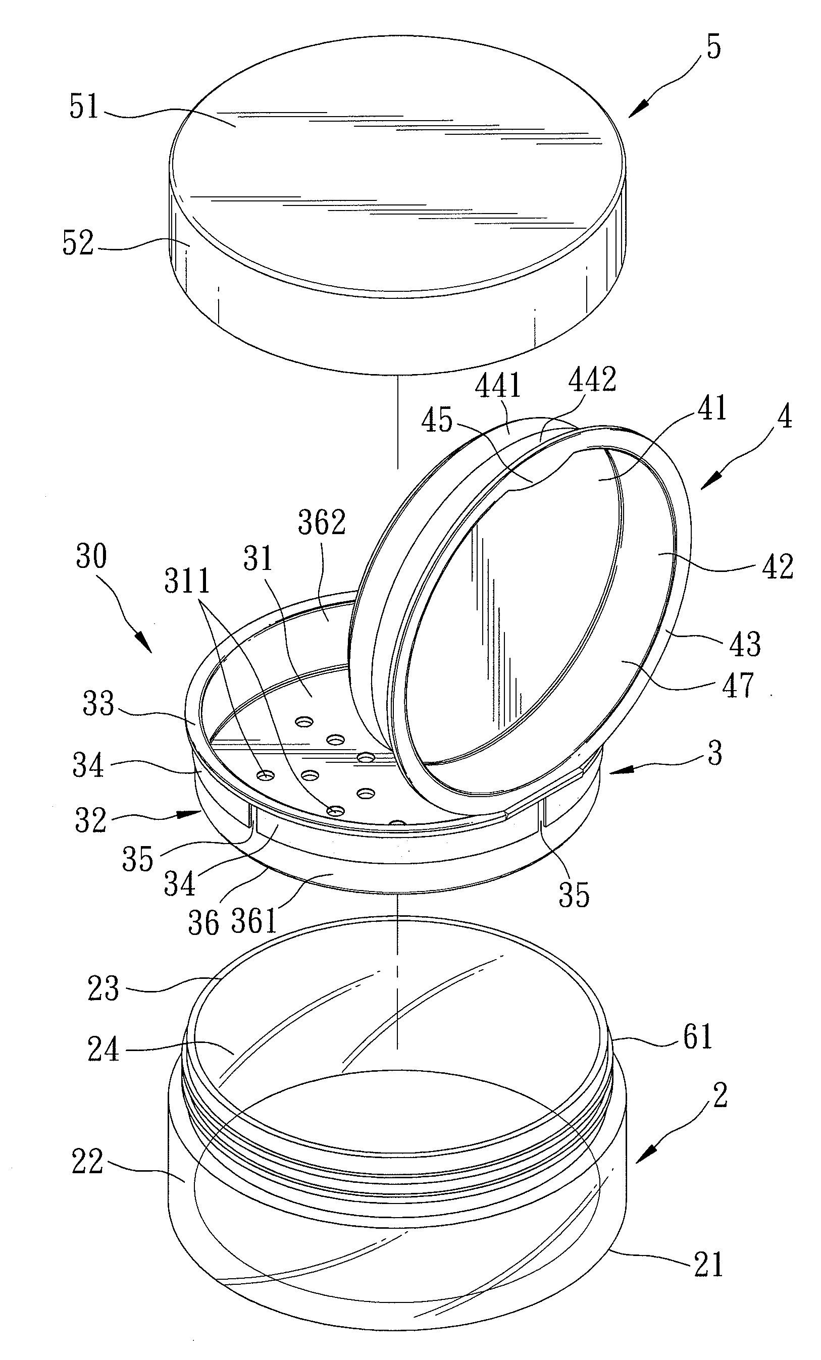
[0020]As shown in FIGS. 3 to 5, a first preferred embodiment of a powder container according to the present invention includes a container body 2, an insert unit 30, and a cover member 5.

[0021]The container body 2 includes a round end wall 21, and an annular side wall 22 extending upwardly from a periphery of the end wall 21 and cooperating with the end wall 21 to define an inner space 24 for disposal of, for example, face powder therein. An opening 23 defined by a top end of the annular side wall 22 is in spatial communication with the inner space 24. The annular side wall 22 is formed with an external thread 61 at a top portion thereof.

[0022]The insert unit 30 includes a first insert member 3 and a second insert member 4. The first insert member 3 is in the form of a sifter, and has a first surrounding wall 32...


PUM


Abstract

A powder container includes a container body and first and second insert members. The container body has an inner space for disposal of powder therein. The first insert member has a first surrounding wall inserted fittingly into the inner space, and a first bottom wall formed with at least one through hole. The second insert member has a second bottom wall inserted into the inner space and disposed on the first bottom wall, and a second surrounding wall extending upwardly from the second bottom wall and disposed fittingly and disengageably on the first surrounding wall of the first insert member for blocking passage of the powder to an external environment through the at least one through hole.

Description

CROSS-REFERENCE TO RELATED APPLICATION[0001]This application claims priority of Taiwanese Application No. 100133392, filed on Sep. 16, 2011.BACKGROUND OF THE INVENTION[0002]1. Field of the Invention[0003]The invention relates to a powder container, more particularly to a powder container having a reusable powder sealing mechanism.[0004]2. Description of the Related Art[0005]As shown in FIGS. 1 and 2, a conventional powder container includes a container body 11 having an inner space for disposal of, for example, face powder 10 therein and an opening 111 in spatial communication with the inner space, a sifter member 12 disposed fittingly in the opening 111 and formed with a plurality of through holes 122 for sifting powder, a one-time plastic film 13 attached removably to the sifter member 12 to seal the through holes 122, and a cover member 14 coupled to the container body 11 for covering the sifter member 12. The sifter member 12 is dish-shaped and defines a receiving space 121 for ...

Claims


Application Information

Patent Timeline
IPC IPC(8): A47G19/24
CPCA45D33/16
Inventor LAI, JENN-SHYANG
Owner LAI JENN SHYANG
Why Eureka
Try Eureka