Coil-tube chunk for a roll feeder

Inactive Publication Date: 2013-03-21
LAI STEVEN
View PDF12 Cites 2 Cited by
  • Summary
  • Abstract
  • Description
  • Claims
  • Application Information

AI Technical Summary

Benefits of technology

[0008]The main objective of the present invention is to provide a coil-tube chunk for a r

Problems solved by technology

In addition, the damaged coil tube 54 ca

Method used


Image

  • Coil-tube chunk for a roll feeder
  • Coil-tube chunk for a roll feeder
  • Coil-tube chunk for a roll feeder

Examples


Example

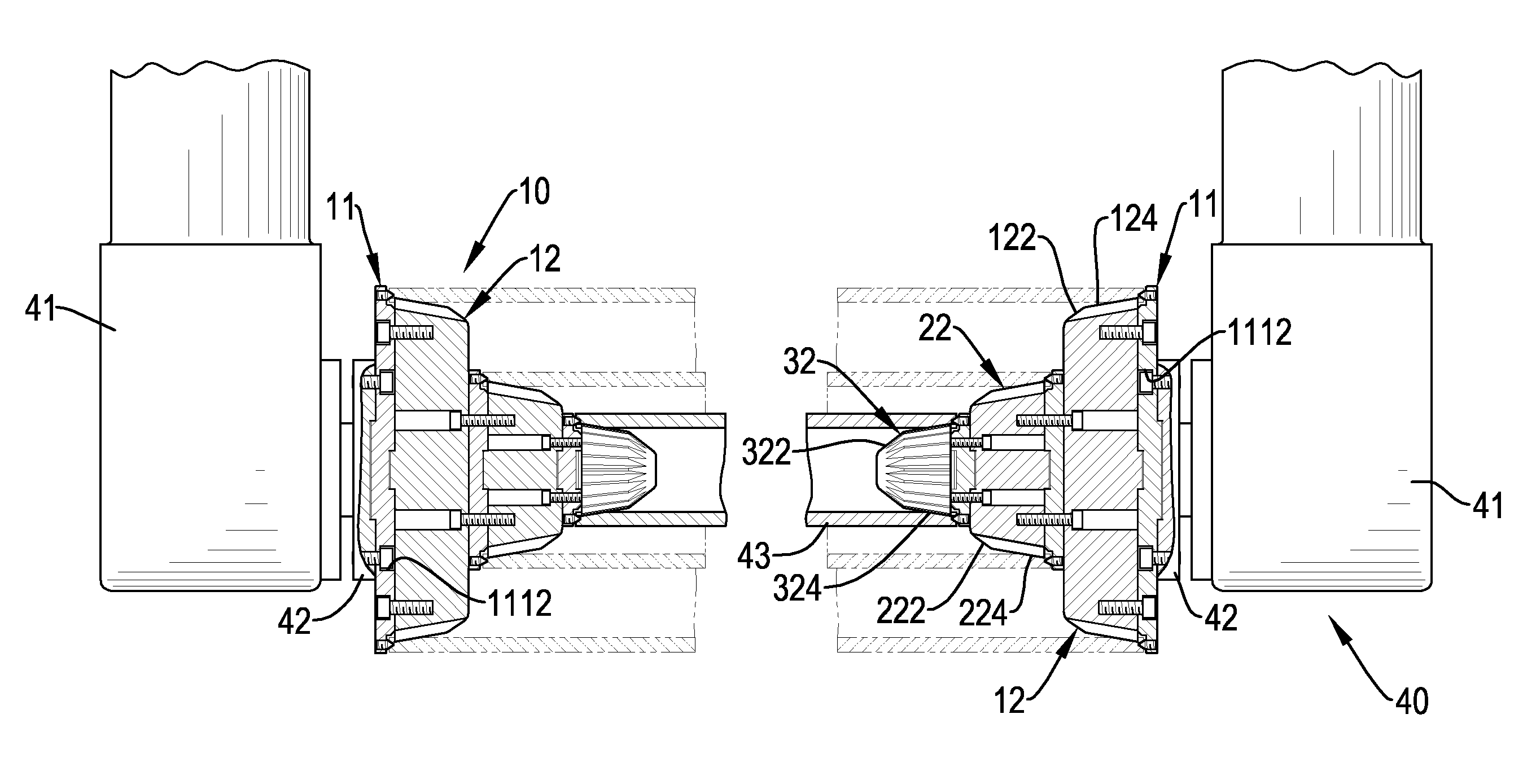
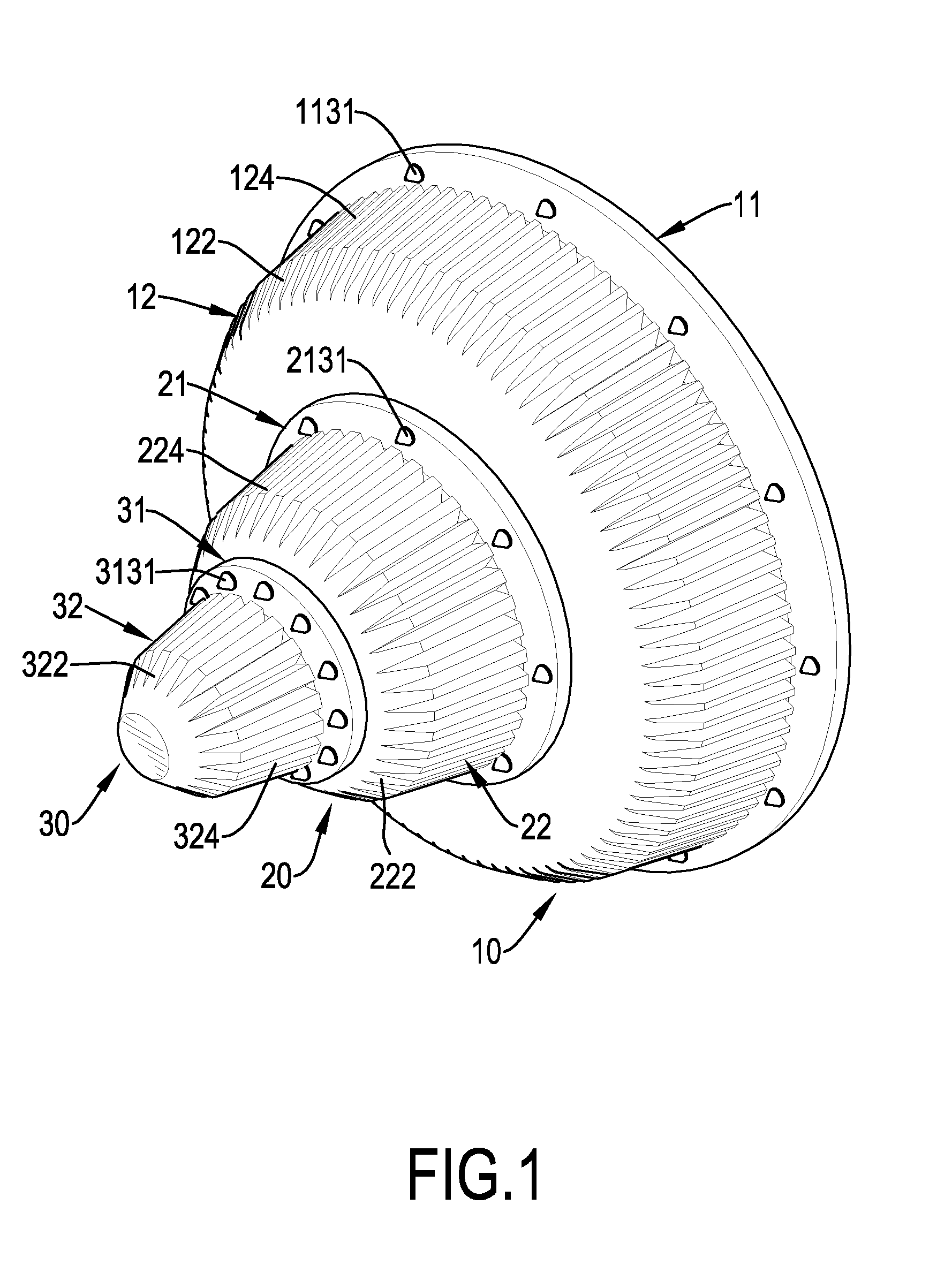
[0022]With reference to FIGS. 1, 2, 3A and 3B, a first embodiment of a coil-tube chunk for a coil tube 43 of a roll feeder 40 in accordance with the present invention comprises a rear colleting device 10, a middle colleting device 20 and a front colleting device 30. The colleting devices 10, 20, 30 are connected to each other concentrically and the diameters of the colleting devices 10, 20, 30 are in a reducing sequence from the rear colleting device 10 to the front colleting device 30.

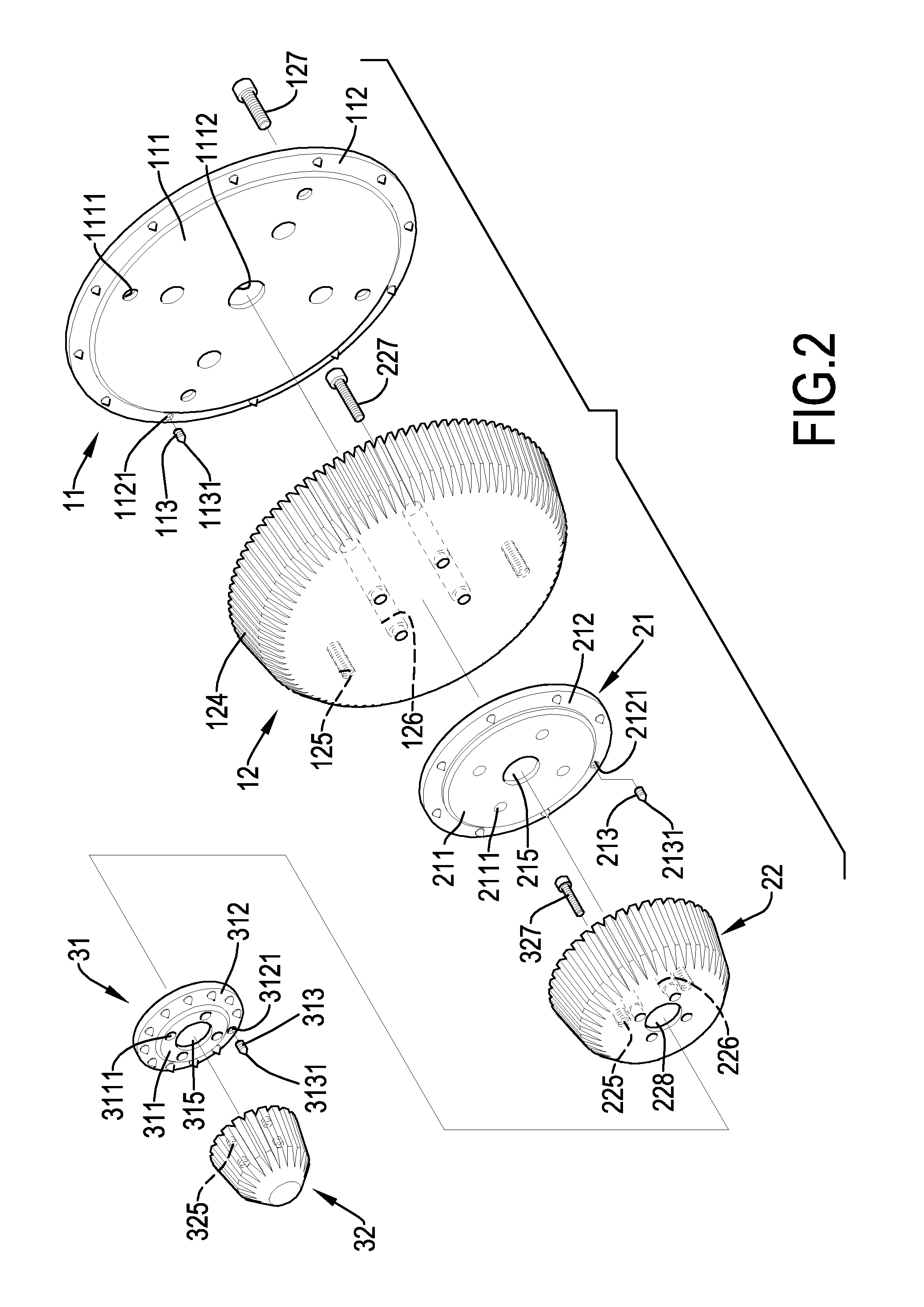
[0023]The rear colleting device 10 has a base 11 and a chunk 12.

[0024]The base 11 is circular and has a front side, a mounting stand 111, a sharp-tooth mount 112, multiple screwing rods 113, a positioning protrusion 114 and an embedded slot 115. The mounting stand 111 is formed on and protrudes from the front side of the base 11 and has a center, a front side, a rear side, multiple bolt-holes 1111 and multiple connecting holes 1112. The bolt-holes 1111 are formed through the sides of the mounting stan...

Example

[0045]With reference to FIGS. 6, 7, 8A and 8B, a second embodiment of a coil-tube chunk 60 for a roll feeder 70 in accordance with the present invention has a base 61 and a chunk 62.

[0046]The base 61 is circular and has a rear side, a front side, a mounting stand 611, a sharp-tooth mount 612, multiple screwing rods 613, a positioning protrusion 614 and an embedded slot 615.

[0047]The mounting stand 611 is circular, is formed on and protrudes from the front side of the base 61 and has a center, a front side and a bolt-hole 6111. The bolt-hole 6111 is formed through the center of the mounting stand 611. The sharp-tooth mount 612 is formed on the front side of the base 61 around the mounting stand 611 and has a front side and multiple screwed holes 6121. The screwed holes 6121 are formed in the front side of the sharp-tooth mount 612 at intervals around the mounting stand 611. The screwing rods 613 are respectively and securely mounted in the screwed holes 6121 of the sharp-tooth mount ...


PUM


Abstract

A coil-tube chunk for a roll feeder has at least one colleting device. Each of the at least one colleting device has a base and a chunk. The base has a mounting stand, a sharp-tooth mount and multiple screwing rods. The mounting stand is formed on and protrudes from the base. The sharp-tooth mount is formed on the base around the mounting stand. The screwing rods are respectively and securely mounted on the sharp-tooth mount. The chunk is mounted securely on the base and has a guiding face, multiple grooves and multiple engaging teeth. The guiding face is aslantly formed on an external surface of the chunk. The grooves are formed in the external surface and the guiding frace of the chunk at intervals. The engaging teeth are formed on the external surface and the guiding face of the chunk between the grooves.

Description

BACKGROUND OF THE INVENTION[0001]1. Field of the Invention[0002]The present invention relates to a coil-tube chunk, and more particularly to a coil-tube chunk for a roll feeder that can provide a preferred holding effect to a coil tube of the roll feeder.[0003]2. Description of Related Art[0004]With reference to FIG. 9, a conventional roll feeder 50 has a coil tube 54 and two rolling arms 51 set to face each other at an interval to hold the coil tube 54. The coil tube 54 may be a paper tube and has two ends, an internal surface and two operational metal rings. The metal rings are mounted on the internal surface of the coil tube 54 at the ends of the coil tube 54. Each rolling arm 51 has a lower end, an inner side, a driving head 52 and a coil-tube chunk 53. The driving head 52 is rotatably mounted on the inner side of the rolling arm 51 at the lower end of the rolling arm 51, is driven by a motor and has an inner end. The coil-tube chunk 53 is conic, is securely and concentrically m...

Claims


Application Information

Patent Timeline
IPC IPC(8): F16C13/00
CPCB65H75/08B65H19/126B65H2220/04B65H2220/01B65H2511/14
Inventor LAI, STEVEN
Owner LAI STEVEN
Why Eureka
Try Eureka