
End Effector with Internal Valve

Active Publication Date: 2013-04-04
AMF AUTOMATION TECH
View PDF5 Cites 5 Cited by
  • Summary
  • Abstract
  • Description
  • Claims
  • Application Information

AI Technical Summary

Benefits of technology

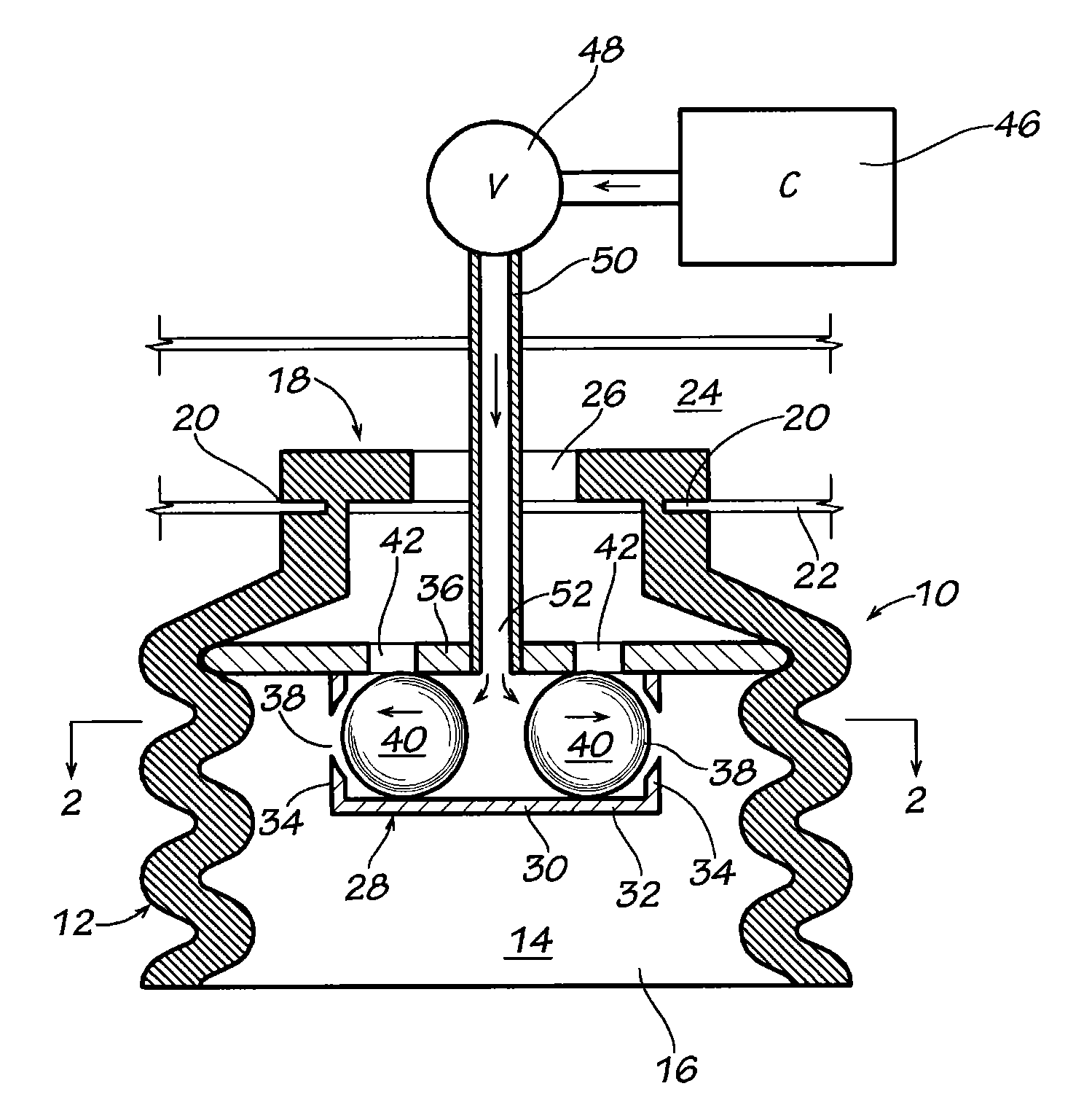
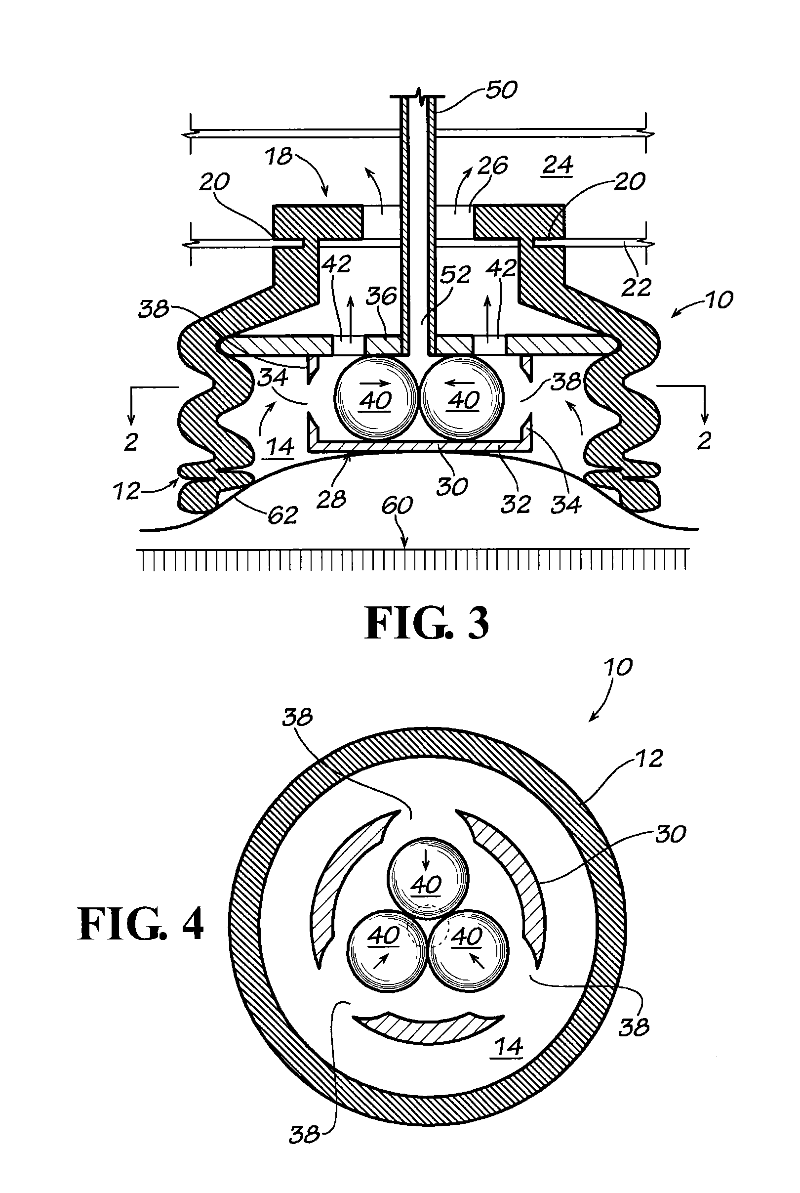
The patent is about a valve that prevents air from moving into a container where a vacuum is being created. This valve uses ball valves and a bottom wall that acts as a ceiling to the interior of a bellows. This prevents the plastic bag or other flexible container from being stretched too much during suction. Additionally, the patent also describes how the valve prevents the plastic wrapper of the work product from blocking the air passages of the bellows, even if it is stretched upwardly during suction.

Problems solved by technology

The suction cups that are not in communication with the vacuum source cannot pick the work products in that picking zone.
This is not desirable in that it sometimes stretches the plastic bags and may even rupture the plastic bags while the work product is attached to the end effector.

Method used


Image

  • End Effector with Internal Valve
  • End Effector with Internal Valve
  • End Effector with Internal Valve

Examples


Embodiment Construction

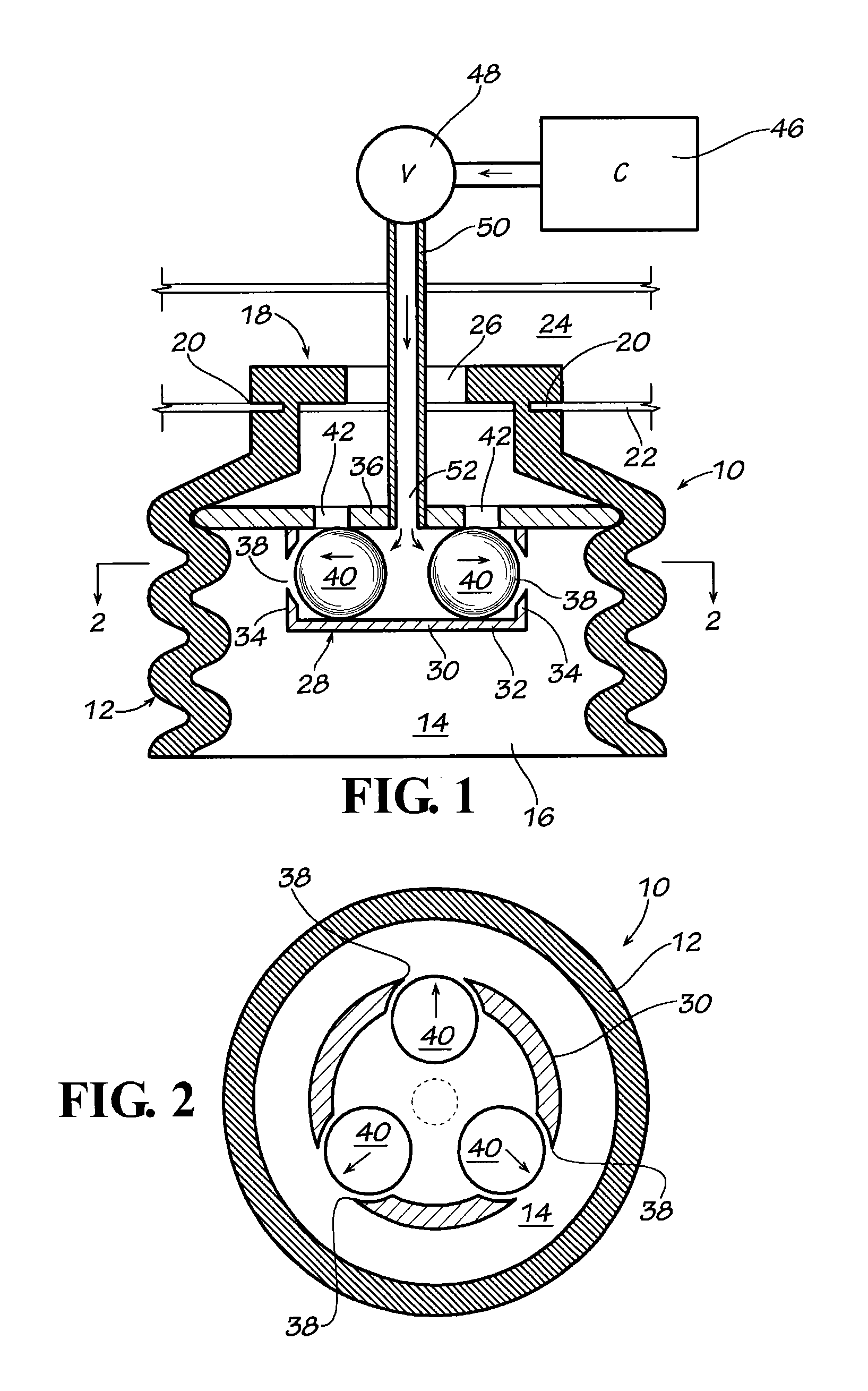
[0030]Referring now in more detail to the drawings, in which like numerals indicate like parts throughout the views, FIG. 1 illustrates a bellows 10 and includes a circular side wall 12 that is formed in a series of vertically spaced circular ribs. The side wall of the bellows defines an interior space 14, having an open end 16 for engaging work products and a mounting end 18 opposite to said open end for mounting to the vacuum plenum 24.

[0031]The mounting end 18 of the bellows includes a circular outwardly facing groove 20 that is mounted about a circular opening in the panel 22 of a vacuum plenum 24. A low air pressure outlet opening 26 is formed in the mounting end 18 of the bellows. It allows the interior space 14 of the bellows to communicate with the vacuum air in the vacuum plenum 24.

[0032]A valve 28 is positioned in the interior space 14 of the bellows 10.

[0033]Valve 28 includes a valve housing 30 that has a bottom wall 32, a circular side wall 34, and a top wall 36. At leas...


PUM


Abstract

A bellows 10 is configured for connection to an end effector of a robot and includes a valve 28 supported in the interior space of the bellows. A flow of low pressure air is induced from inside the bellows into a vacuum plenum 24 for retrieving a work product by the open end 16 of the bellows. High pressure air is moved through a conduit 50 into the valve to terminate the flow of low pressure air and terminate the suction applied by the bellows to the work product.

Description

CROSS REFERENCE[0001]This is a continuation-in-part of U.S. patent application Ser. No. 12 / 763,242 filed in the U.S. Patent & Trademark Office on Apr. 20, 2010, now U.S. Pat. No. 8,251,415, issued Aug. 28, 2012, and a continuation-in-part of U.S. patent application Ser. No. 13 / 287,184 filed in the U.S Patent & Trademark Office on Nov. 2, 2011.FIELD OF THE INVENTION[0002]This disclosure concerns robotic packaging devices that include an end effector that can be used for collecting work products of different shapes and sizes, usually for placing the products in different patterns into a receptacle, such as a shipping container.BACKGROUND OF THE DISCLOSURE[0003]When placing work products in a shipping container, it is desirable to place several work products at a time in the container and, in some instances, the work products must be collected in a desired pattern of the products for fitting into the container of a specific size and shape.[0004]For example, in the bakery industry a pro...

Claims


Application Information

Patent Timeline
IPC IPC(8): B25J15/06
CPCY10S901/40B25J15/0633
Inventor LOMERSON, JR., ROLANDNORTON, MICHAEL W.
Owner AMF AUTOMATION TECH
Learn More