Hand-held cutting tools

a technology cutting tools, which is applied in the field of hand-held cutting tools, can solve the problems of weight balance and operability degradation

Active Publication Date: 2013-04-25
MAKITA CORP
View PDF22 Cites 27 Cited by
  • Summary
  • Abstract
  • Description
  • Claims
  • Application Information

AI Technical Summary

Benefits of technology

[0009]In one aspect according to the present teachings, a hand-held cutting tool may include a handle and a battery pack. The handle has a rear portion with respect to a work proceeding direction along which the cutti...

Problems solved by technology

As a result, it is necessary for the rear portion of the handle to have a large size in the forw...

Method used


Image

  • Hand-held cutting tools
  • Hand-held cutting tools
  • Hand-held cutting tools

Examples


first embodiment

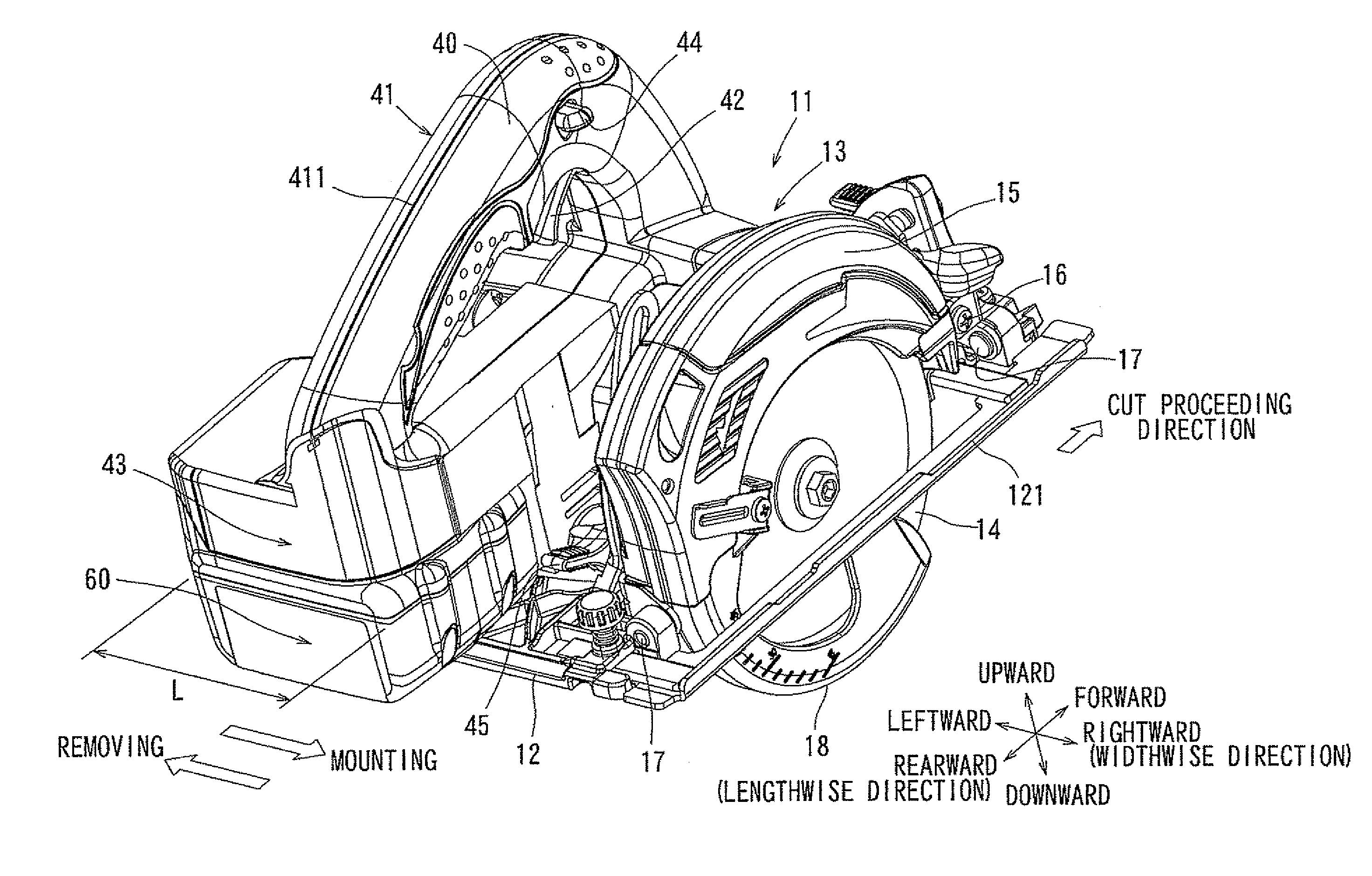
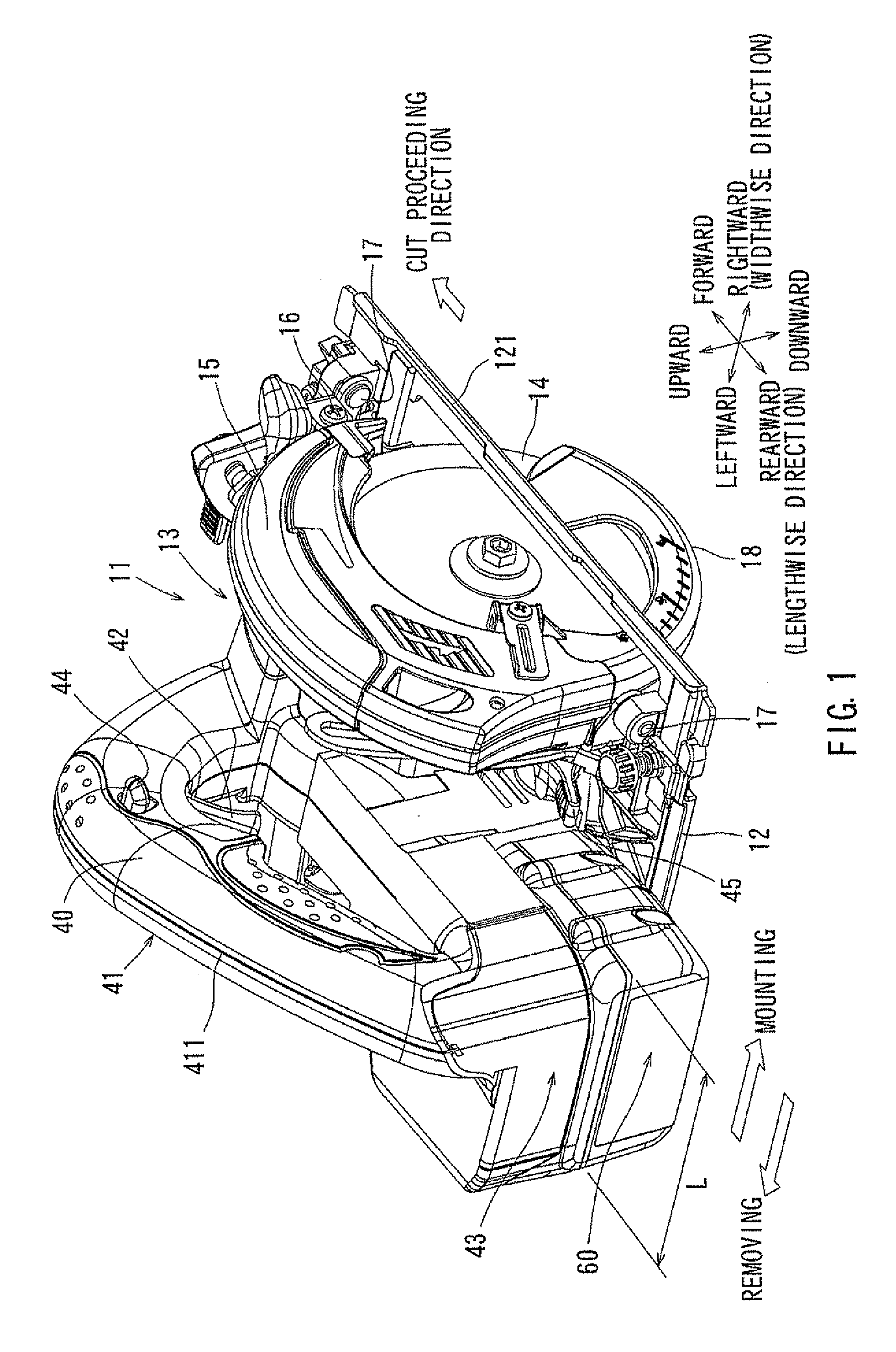
[0033]A first embodiment will now be described with reference to FIGS. 1 to 6. Referring to FIGS. 1 to 6, there is shown a cutting tool 11 known as a circular saw, as an example of a hand-held cutting tool. The cutting tool 11 may generally include a substantially rectangular base 12 and a tool unit 13 that may be supported on the upper surface of the base 12. The base 12 is designed for contacting with an upper surface of a workpiece (not shown). A sub-base 121 may be detachably mounted to a right side of the base 12. The sub-base 121 may be provided for convenience of performing a so-called “edge cutting operation.” For the purpose of explanation, a work proceeding direction (i.e., a cut proceeding direction) that is a direction, along which the cutting tool 11 is moved for performing a cutting operation, will be determined as a forward direction.

[0034]The tool unit 13 may include a circular saw blade 14 and a blade case 15. The blade case 15 may cover substantially the upper circ...

second embodiment

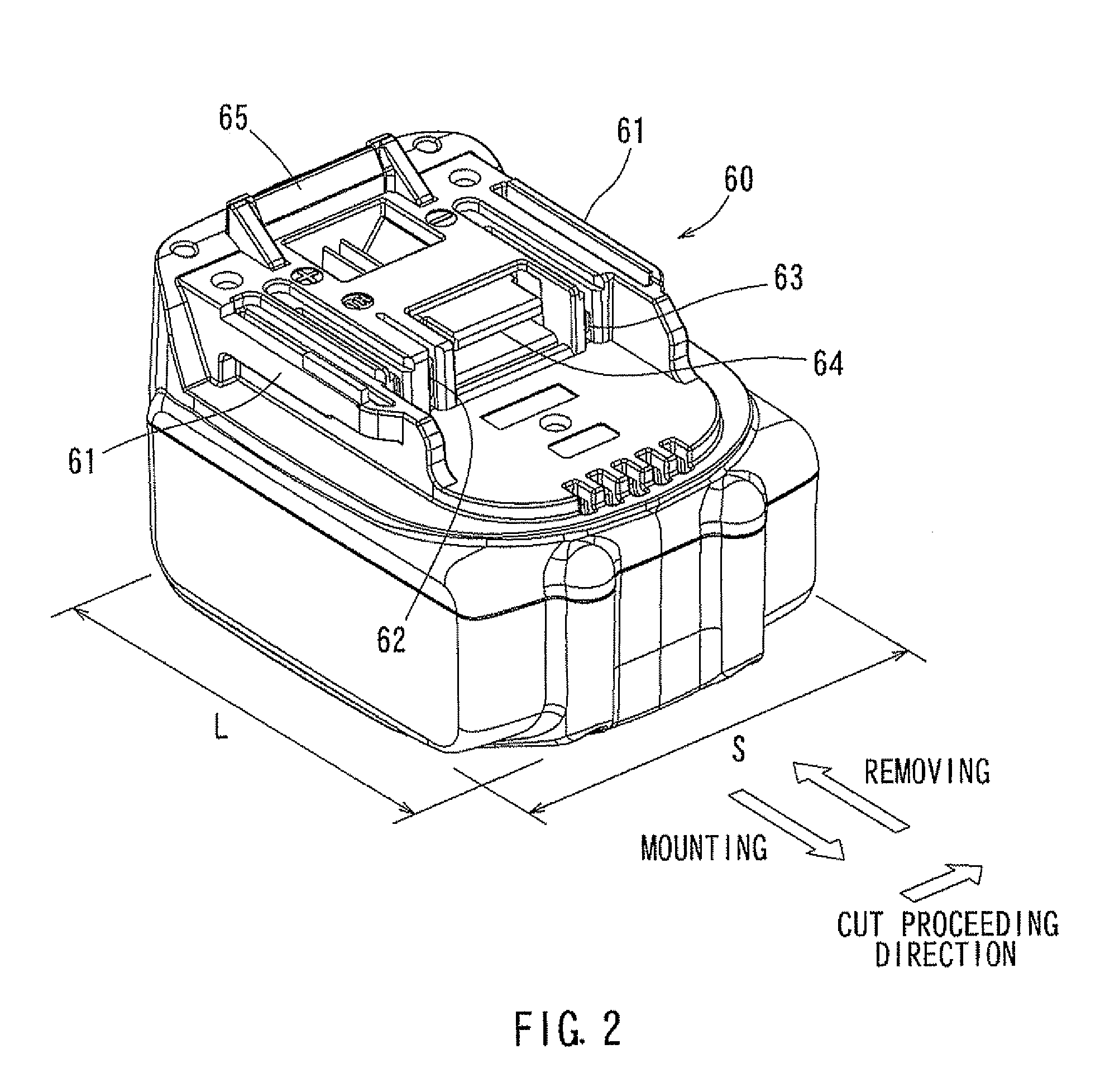
[0062]With the cutting tool 11A of the second embodiment, the motor shaft 24 and the output shaft 46 are positioned within the length of the handle 41A in the work proceeding direction. Therefore, the cutting tool 11A can be configured to be compact with respect to the cut proceeding direction. Hence, the cutting tool 11A can be improved in its operability. In addition, the motor shaft 24 and the output shaft 36 are positioned forwardly of the position 600 of the gravity center of the battery 60 with respect to the work proceeding direction, while the motor shaft 24 and the output shaft 36 are positioned within the range of length of the handle 41A as described above. Therefore, the cutting tool 11A may be improved in the weight balance with respect to the forward and rearward direction along the work proceeding direction. Therefore, the operability of the cutting tool 11A may be further improved. Further, the intermediate shaft 32 is positioned forwardly of the motor shaft 24 and t...


PUM

PropertyMeasurementUnit
Lengthaaaaaaaaaa
Widthaaaaaaaaaa
Gravityaaaaaaaaaa

Abstract

A hand-held cutting tool may include a handle and a battery pack. The handle has a rear portion with respect to a work proceeding direction along which the cutting tool is moved for performing a cutting operation. When the battery pack is mounted to the rear portion of the handle, the longitudinal direction of the battery pack extends non-parallel with the work proceeding direction.

Description

[0001]This application claims priority to Japanese patent application serial number 2011-230429 and 2012-212325, the contents of which are incorporated herein by reference.BACKGROUND OF THE INVENTION[0002]1. Field of the Invention[0003]Embodiments of the present invention relate to cutting tools, in particular to hand-held cutting tools having batteries as power sources.[0004]2. Description of the Related Art[0005]JP-A-2010-201598, JP-A-2008-18498 and JP-A-61-8289 disclose known cutting tools. Each of these documents discloses a portable circular saw having a base for contacting with an upper surface of a workpiece, and a tool unit supported on the base. The tool unit includes a circular saw blade, an electric motor for rotating the circular saw blade, and a handle that can be grasped by the user for moving the circular saw.[0006]As disclosed in the above documents, a battery may be typically mounted to the rear portion of the handle or a position adjacent to the rear portion. The b...

Claims


Application Information

Patent Timeline
IPC IPC(8): B25F5/02B27B9/00
CPCB27B9/00B23D47/12
Inventor NAITO, TSUTOMUINAYOSHI, HIROTOMO
Owner MAKITA CORP
Why Eureka
Try Eureka