Denture and method and apparatus of making same

a technology of dental prosthesis and occlusion, which is applied in the direction of dental prosthesis, manufacturing tools, impression caps, etc., can solve the problems of high labor intensity, improper occlusion (upper and lower teeth engagement), and high labor intensity in the manufacture of dental prosthesis, so as to increase the likelihood of patient acceptance and optimize the fit and aesthetics

Active Publication Date: 2013-04-25
GLOBAL DENTAL SCI
View PDF3 Cites 66 Cited by
  • Summary
  • Abstract
  • Description
  • Claims
  • Application Information

AI Technical Summary

Benefits of technology

[0047]If it is desirable to fabricate a temporary “try-in” denture with resin teeth for a test fit before fabricating a long-term denture, the method and apparatus can be used to fabricate the try-in denture as described previously. A methacrylate denture base material is milled to form sockets where the teeth will be fabricated. The sockets are subsequently filled with moldable wax. Then the apparatus mills a cavity whereby tooth-colored resin is placed in the cavity to form the teeth. Because the synthetic teeth material is resin in a socket made of wax, in the dental office, a dentist can fit the try-in denture to the patient, and make final adjustments to optimize its fit and aesthetics. Additionally, the patient can see the color and translucency of the final denture teeth before the final denture is made, thereby increasing the likelihood of patient acceptance at the final appointment. Then the final-adjusted try-in denture can be scanned in 3D and digitally compared to the original “wax

Problems solved by technology

Heretofore, the manufacturing of dental prostheses has been a highly labor intensive process requiring multiple fittings to a patient in need of them, and many steps that must be performed at the hands of skilled artisans.
It can be seen that in the above highly labor-intensive process, each of these steps introduces a potential for a processing error.
Even the slightest error, such as the investment being too cool, or the powder/water ratio of the investment being incorrect may cause the crown to fit too tightly in the patient's mouth, resulting in improper occlusion (upper and lower teeth engagement).
The crown may thus have to be scrapped or reworked through at least one iteration of additional process steps at considerable cost to the patient, dentist, and/or manufacturing lab.
For example, subtle irregularities often found in anterior (front) teeth are difficult to replicate using CAD/CAM processes.
Manual methods of making anterior fixed prosthetics enable unlimited aesthetic options, only limited by the creativity of the artisan (dental laboratory technician).
Some CAD/CAM techniques involve the use of milling a monolithic block of ceramic that does not deliver optimal aesthetics (example: too opaque), especially for anterior applications.
However, this manual step may defeat the primary benefit of CAD/CAM: precise dimensional accuracy.
However, this system generates only a CAD replica in plastic (made by a 3D printer), which requires subsequent extensive processing to obtain a metal partial denture framework.
Hence there are still many error-prone steps after the CAD replica is made that can result in a poorly-fitting partial denture framework.
However, the materials available to use in 3-dimensional printers are neither as dense nor cross-linked like a normal plastic artificial tooth.
Hence a problem remains with the resulting dentures because the denture teeth that are made with available 3D printing plastic materials are not sufficiently wear-resistant.
A problem with this approach is that most of the teeth must be adjusted to some extent to fit within the space required in order for the denture to properly occlude with the opposing arch of the opposing d

Method used


Image

  • Denture and method and apparatus of making same
  • Denture and method and apparatus of making same
  • Denture and method and apparatus of making same

Examples


Embodiment Construction

[0063]For a general understanding of the present invention, reference is made to the drawings. In the drawings, like reference numerals have been used throughout to designate identical elements.

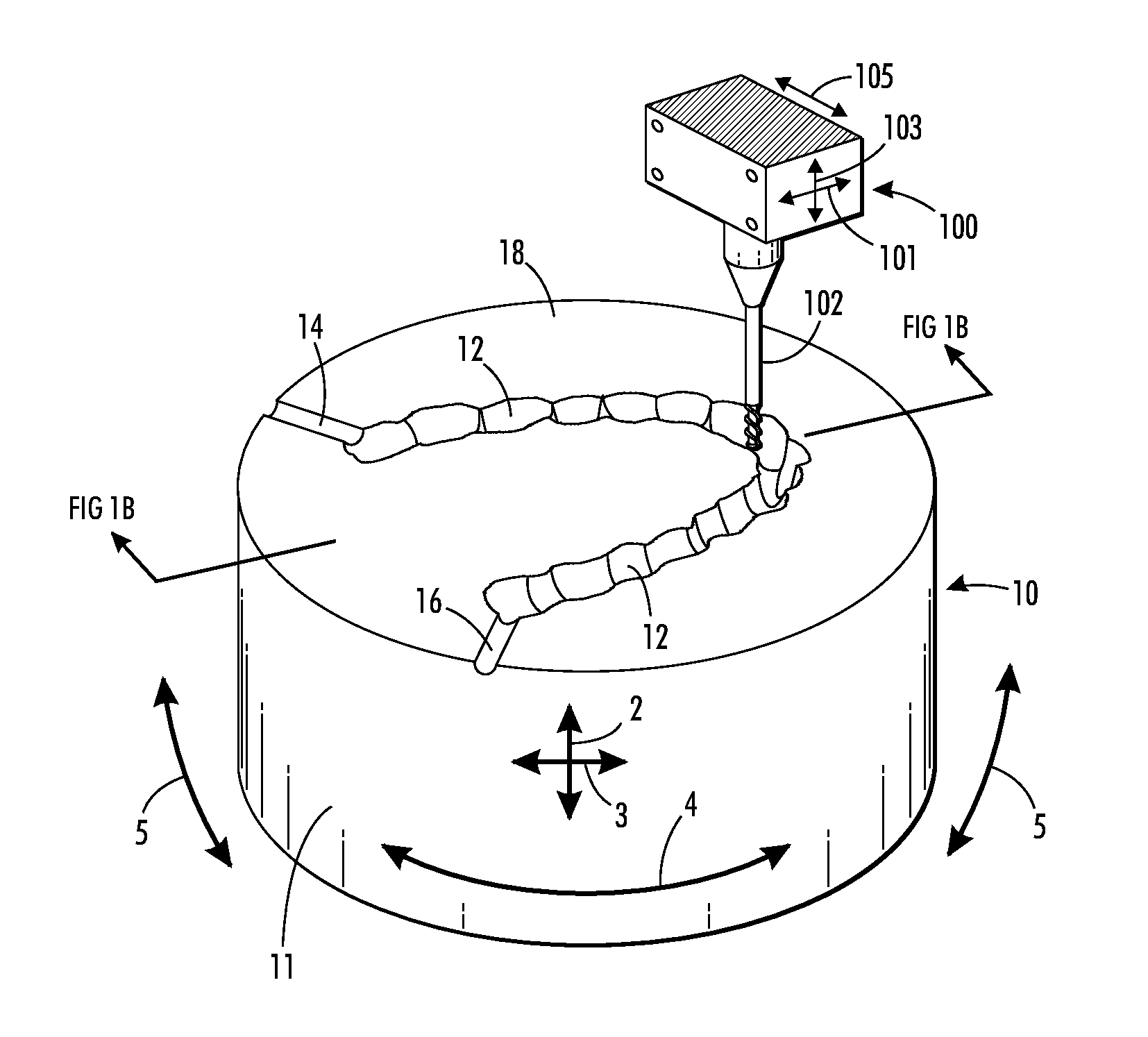
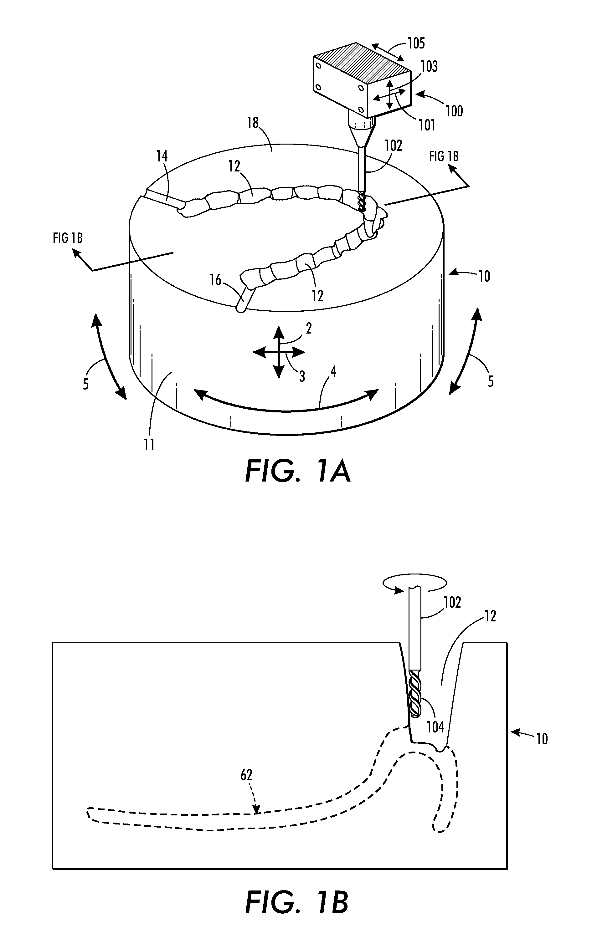
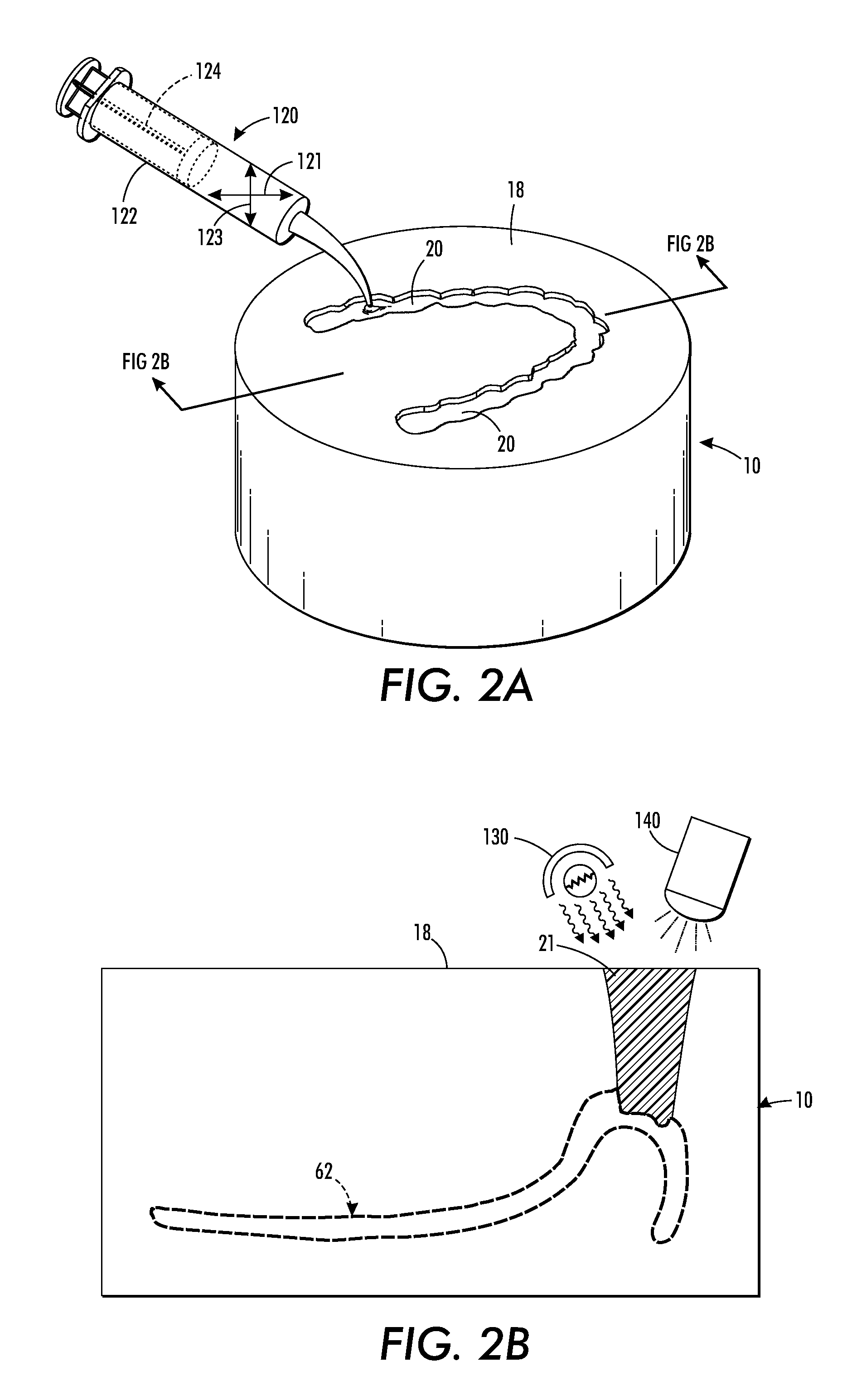
[0064]In accordance with the present disclosure, there are provided a method and an apparatus for making a dental prosthesis, such as a denture, by using a block of denture base material as a receptacle for molding the teeth of the denture. The block of denture base material is milled by a milling machine or other material removal device to create a mold for the teeth, dispensing liquid tooth material in the mold and curing it into solid tooth material, and milling the combination of cured solid tooth material in the mold and denture base material to form the denture.

[0065]Turning first to FIGS. 1A and 1B, a block 10 of denture base material is shown in the process of having a first cavity 12 being formed therein. The first cavity 12 is formed to match the generally U-shaped contour of natura...


PUM

PropertyMeasurementUnit
Dimensionaaaaaaaaaa
Translucencyaaaaaaaaaa

Abstract

A method for making a denture comprising a base and a plurality of teeth joined thereto. The method comprises forming a first cavity in a block of a denture base material, the first cavity being formed to match the contour of natural teeth as arranged on maxillae or on a mandible; filling the first cavity with a first fluid synthetic tooth material and solidifying the first fluid synthetic tooth material into a first solid synthetic tooth material; removing a portion of the first solid synthetic tooth material to form the plurality of teeth; and removing a portion of the block of denture base material to form the denture base. The steps of the method may be implemented by a computer. An apparatus for making the denture according to certain embodiments of the method, and a denture comprised of a base and artificial teeth are also disclosed.

Description

CROSS-REFERENCE TO RELATED PATENT APPLICATIONS[0001]This application claims priority from U.S. Provisional Patent Application No. 61 / 539,970, filed Sep. 27, 2011, the disclosure of which is incorporated herein by reference.BACKGROUND[0002]1. Technical Field[0003]Dental prostheses and apparatus and methods of manufacturing them. In particular, computer-implemented methods of manufacturing dental prostheses, a computer-aided system for manufacturing dental prostheses, and dental prostheses made by the system and method.[0004]2. Description of Related Art[0005]Heretofore, the manufacturing of dental prostheses has been a highly labor intensive process requiring multiple fittings to a patient in need of them, and many steps that must be performed at the hands of skilled artisans. The dental prostheses may be a complete upper and / or lower set of prosthetic teeth and their mountings, i.e., dentures, or partial dentures, crowns, bridges, and the like.[0006]By way of illustration, the follo...

Claims


Application Information

Patent Timeline
IPC IPC(8): A61C13/20A61C13/10
CPCA61C9/0053A61C13/0004A61C13/0006A61C13/0022A61C13/01A61C13/087A61C19/003A61C13/10A61C13/1003A61C13/04A61C13/081A61C13/34A61C13/09B33Y80/00
Inventor HOWE, DEVON O.
Owner GLOBAL DENTAL SCI
Why Eureka
Try Eureka