Automatic beauty therapy equipment

Inactive Publication Date: 2013-04-25
METAL INDS RES & DEV CENT
View PDF1 Cites 6 Cited by
  • Summary
  • Abstract
  • Description
  • Claims
  • Application Information

AI Technical Summary

Benefits of technology

[0010]Further object of the present invention is to provide an automatic beauty therapy equipment in which the controller is used to set therapy parameter so that the therapy element moves vertically and swing with the curved profile of the therapy area and keeps a suitable therapy distance from the therapy area to have a precis

Problems solved by technology

However, such a manual operation still has the following defects:
2. Because the therapy element is operated manually, a fatigue will ge

Method used


Image

  • Automatic beauty therapy equipment
  • Automatic beauty therapy equipment
  • Automatic beauty therapy equipment

Examples


Embodiment Construction

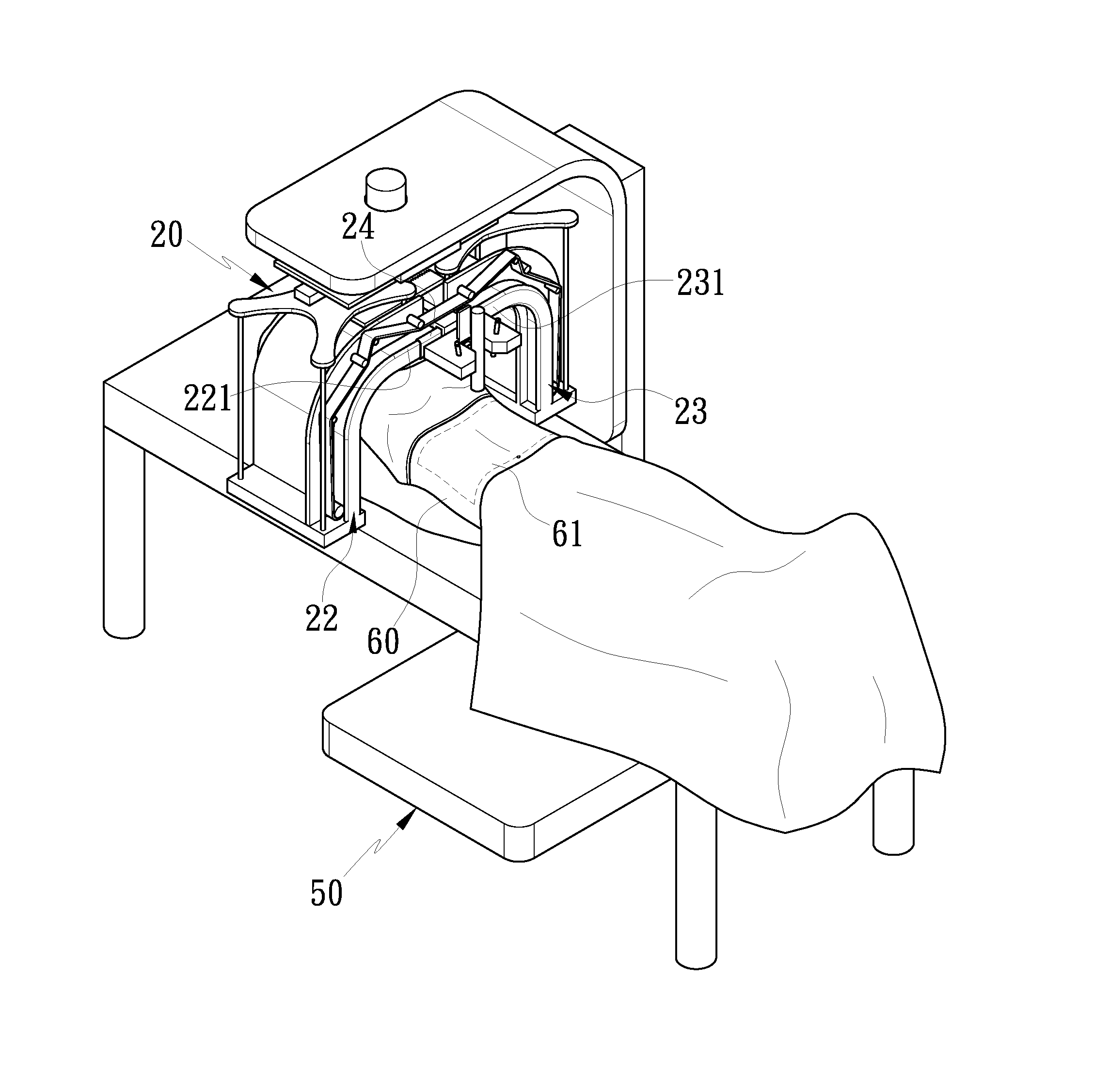
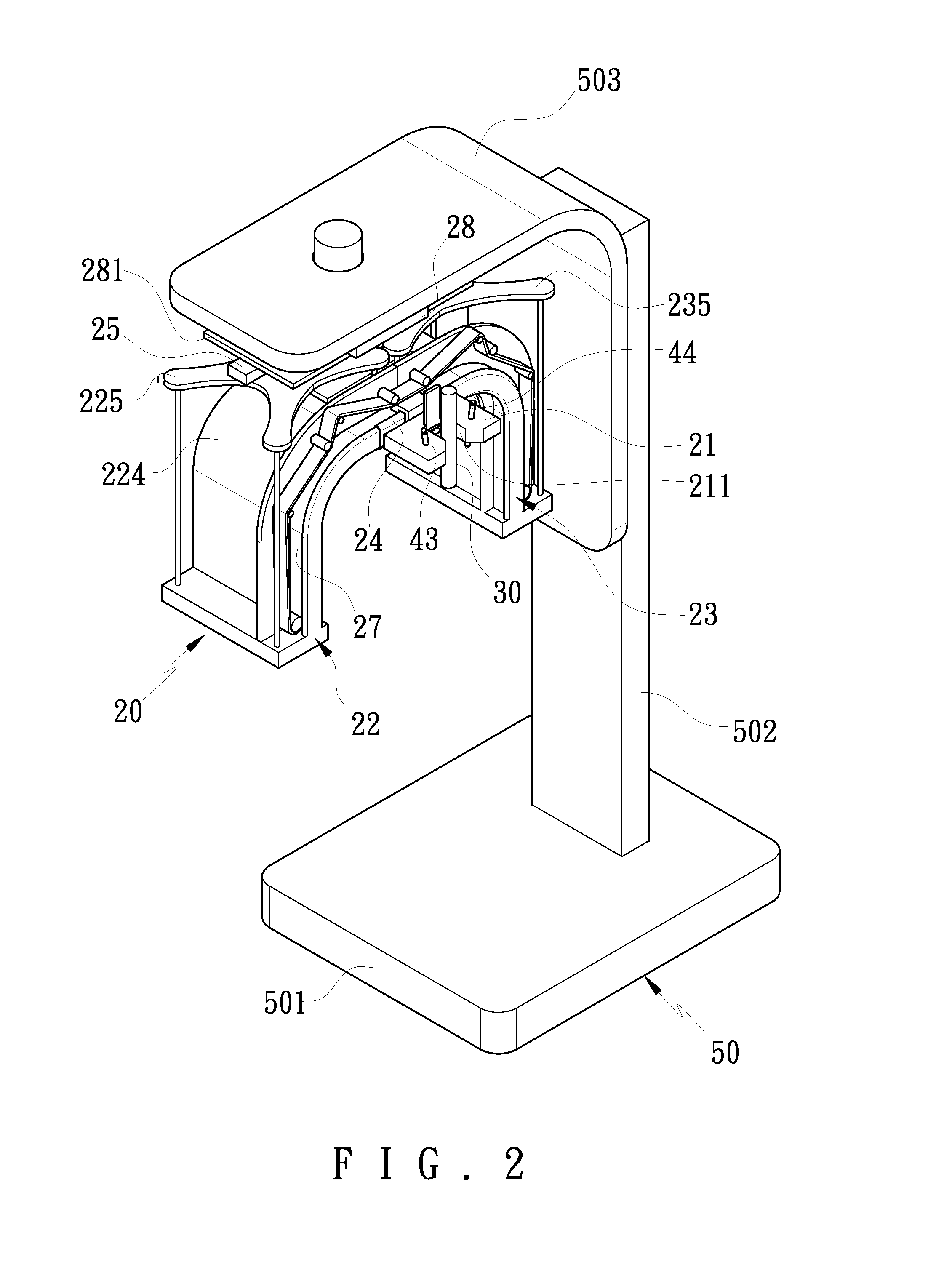
[0026]Referring to FIGS. 2-6, an automatic beauty therapy equipment according to a preferred embodiment of the present invention comprises a displacement driving device 20, a therapy device, a controlling device 40, and a supporting member 50; the displacement driving device 20 includes a pedestal 21 to be driven by a displacing mechanism so as to move axially, and the pedestal 21 includes a receiving portion 211 disposed on one side thereof and an actuating block 212 mounted on another side thereof and connected onto the displacing mechanism so that the pedestal 21 moves axially; in this embodiment, the displacing mechanism includes a first guiding set and a second guiding set, wherein the first guiding set is coupled with the pedestal 21 and formed in a door shape to drive the pedestal 21 to displace straightly or curvedly in a first-axis direction and a second-axis direction, the second guiding set is connected with the first guiding set to drive the pedestal 21 to move straightl...


PUM


Abstract

An automatic beauty therapy equipment contains a displacement driving device including a pedestal to be driven by a displacing mechanism so as to move straightly or curvedly in a first-axis direction, a second-axis direction, and a third-axis direction; a therapy device including a therapy element fixed in the pedestal; a controlling device including a controller electrically connecting with the displacement diving device and the therapy device, the controller being used to control the displacement driving device to urge the therapy element of the therapy device to move straightly or curvedly within a therapy area in the first-axis, the second-axis, and the third-axis directions, and the controller being served to set a therapy area so that the therapy element is driven to move vertically and swing with a curved profile of the therapy area to have a precise and stable beauty therapy in the therapy area.

Description

BACKGROUND OF THE INVENTION[0001]1. Field of the Invention[0002]The present invention relates to automatic beauty therapy equipment in which the therapy element can be operated precisely and stably in the therapy area to achieve a therapy effect well.[0003]2. Description of the Prior Arts[0004]As shown in FIG. 1, a conventional manual therapy element 10 is operated manually to move within a therapy area 11 to irradiate laser energy on skin to have a beauty therapy. However, such a manual operation still has the following defects:[0005]1. When moving therapy element 10 manually, it has to be keep a suitable distance from the therapy area 11, or a beauty therapy effect can not be obtained as the distance between the therapy element 10 and the therapy area 11 is large; yet a burning will happen as distance between the therapy element 10 and the therapy area 11 is small.[0006]2. Because the therapy element is operated manually, a fatigue will generate while operating in a long time.[000...

Claims


Application Information

Patent Timeline
IPC IPC(8): A61B18/18A61B18/20
CPCA61B18/203A61B19/2203A61B2019/461A61B2018/1807A61B2018/00452A61B2018/00791A61B34/30A61B2090/061
Inventor CHANG, YI-SANHSU, CHE-CHANGCHANG, SHYANG-JYECHAO, SHEAU-CHIOU
Owner METAL INDS RES & DEV CENT
Why Eureka
Try Eureka