Irradiation device for therapeutic treatment of skin and other ailments

a technology of irradiation device and skin, applied in the field of irradiation device, can solve problems such as complications in wound healing, achieve the effects of reducing the achievable pulse length, avoiding necrosis of irradiated cells, and reducing heat transition resistan

Inactive Publication Date: 2005-06-07
SPECTROMETRIX OPTOELECTRONICS SYST
View PDF22 Cites 123 Cited by
  • Summary
  • Abstract
  • Description
  • Claims
  • Application Information

AI Technical Summary

Benefits of technology

[0022]The present invention utilizes the discovery that during pulsed irradiation—other than described in the scientific literature—the generation of singlet oxygen during peak power time is higher than during cw-irradiation by several orders of magnitude. Another advantage of high peak powers is the fact that the deeper layers of the skin also receive sufficient irradiation intensity, seeing that usually only a fraction of cw-radiation reaches those deeper layers due to the low penetration depth of blue light. In addition, pulsed radiation energy has a stronger photobiological effect. If we assume an equal cumulated radiation dose of cw-radiation and pulse radiation, and also assume an intensity of 70 mW / cm2 for the cw-radiation, we would see that only 10 mW / cm2 would remain for photobiological effects, since 60 mW / cm2 of the radiation input would be neutralized by dermal antioxidants as a constant off-set. It is obvious that this decrease in photobiological efficiency by constant off-set can be effectively reduced by using pulsed radiation. Pulsed power peaks in the kW power range are only marginally affected by this dermal antioxidant effect. The average energy supply is so chosen as to avoid necrosis of the cells but merely to induce apoptosis. Likewise, the treatment stays below the ablation threshold aimed at in EP 0 565 331 B1. Tissue ablation occurs when energy higher than 2500 J / cm2 is deposited in the tissue within a period of time that does not allow heat exchange between adjacent layers. Due to the time modulation by pulse generation, where the irradiation time is below the relaxation period of the uppermost layer of the skin, in the outer layer of the skin hyperthermia is achieved which can easily be removed. Light in the range of 400-500 nm loses 50% of its energy after 200 μm. The estimated thermal relaxation period for a structure with a diameter of 200 pm is approx. 20 ms, meaning that, assuming a retention period of the light of <20 ms, only the outer layers of the skin are heated without any energy deposition in the deeper layers.
[0053]By increasing the irradiated area, the energy density at the surface decreases so that the duration of the widened irradiation area may be longer. This accomplishes that a larger number of absorbing chromophores can be photochemically excited over a longer time interval than would be possible during a short pulse. The absence of radiation peaks within the radiation area impede the local bleaching resp. the local shortage of oxygen. Furthermore, there is a local maximum in the central area of the irradiation field since the scattering of all rays add and increase the radiation in the central area. Depending on the tissue parameters an the spectrum, the optimal irradiation area has a diameter of more than 4 mm and less than 60 mm since by using large diameters the scattering of the marginal rays does not increase the intensity in the central area. By choosing an optimal beam diameter, a higher intensity in the central irradiation area resp. a higher penetration depth can be achieved. A further widening of the irradiation area leads to a decrease in power density proportional to the increase of the area so that no light reaches the deeper tissue layers. Furthermore, the re-irradiation period of ever larger tissue areas shortens so that heat extraction resp. become more difficult.

Problems solved by technology

Up to now, these have been treated with UV-light, which often leads to temporary improvement, but leads also frequently to complications in wound-healing in the long run.

Method used


Image

  • Irradiation device for therapeutic treatment of skin and other ailments
  • Irradiation device for therapeutic treatment of skin and other ailments
  • Irradiation device for therapeutic treatment of skin and other ailments

Examples


Embodiment Construction

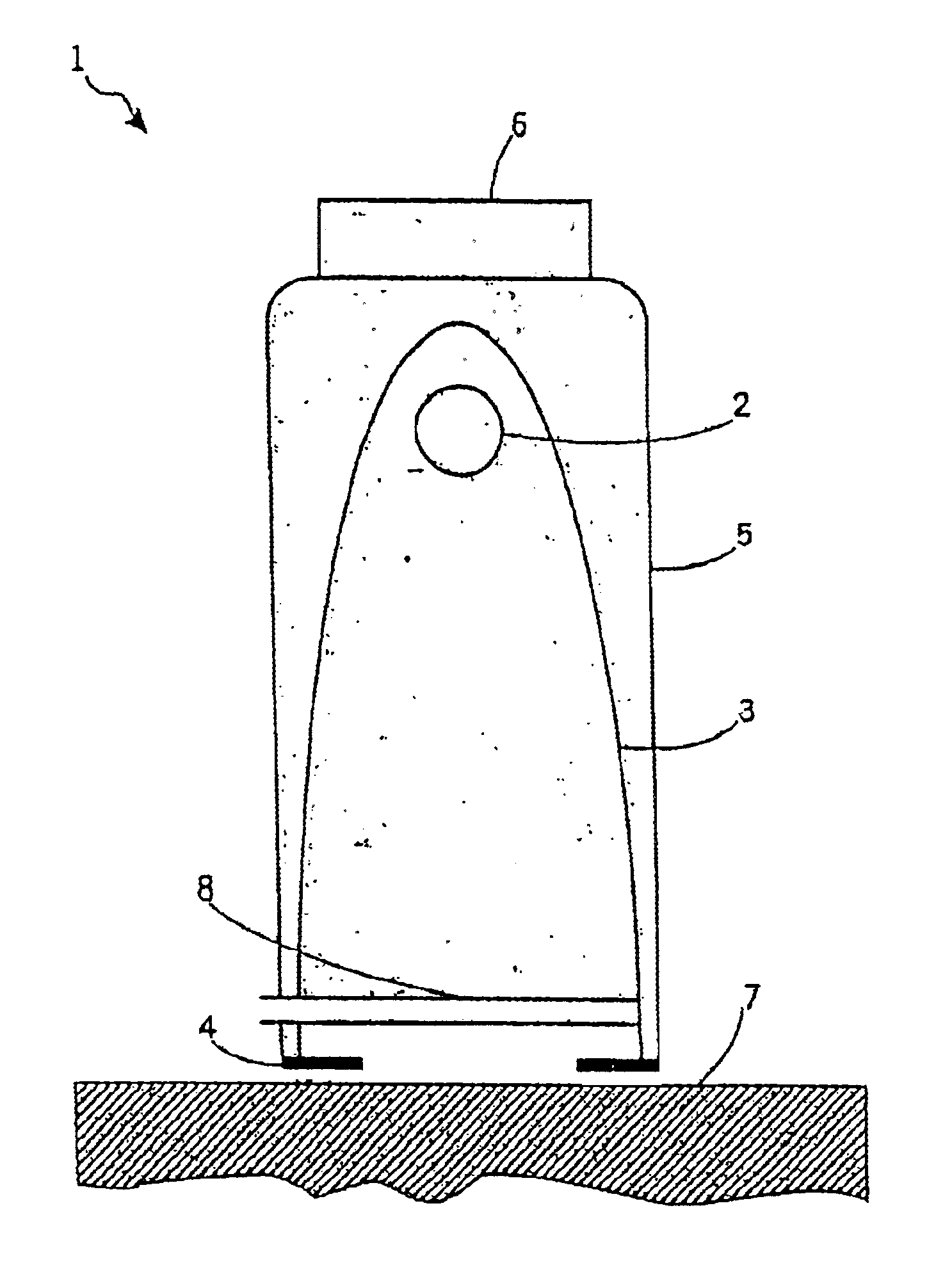
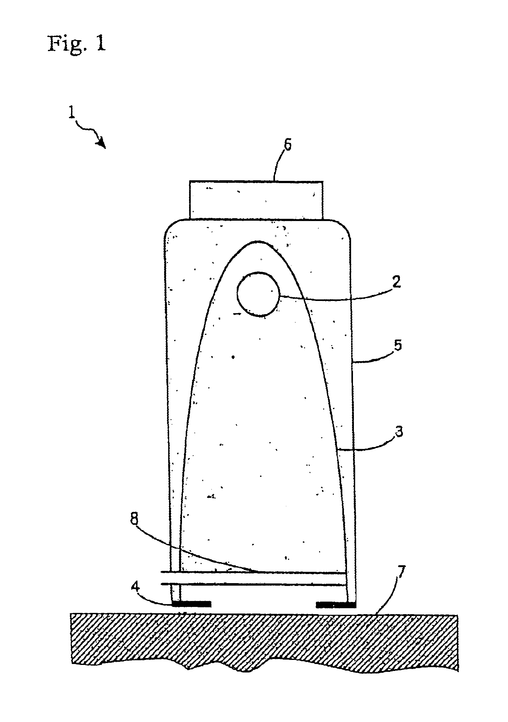
[0068]The irradiation device 1 comprises a broadband irradiation source 2 which is preferably a xenon flashlamp. The irradiation source 2 is mounted in the focus of a parabolic reflector 3 which is open on the side averted from the focus. The exit area at the open end of the parabolic reflector 3 is preferably defined through an adjustable shutter. The adjustable shutter can adjust the area to be irradiated. The irradiation source 2 and the paraboloid reflector 3 are mounted in a housing 5. The housing 5 comprises a handpiece 6 by means of which the irradiation device 1 can be placed on the area to be treated 7. Between the radiation source 2 and the area to be treated 7 there is a luminescent foil 8 arranged which is doped with luminescent particles. The luminescent foil 8 can also be arranged in the proximity of the radiation source 2 or the shutter 4. Preferably, the luminescent foil 8 is arranged in a way that makes it easy to replace. This simplifies the necessary replacement d...


PUM


Abstract

The invention relates to an irradiation device and method for the treatment of totally or partially cell-mediated inflammations of the skin, the connective tissue and the viscera, viral and other infectious diseases such as HIV and prionic infections, fungal infections of the skin and the mucous membranes, bacterial diseases of the skin and the mucous membranes as well hand eczema and anal eczema which comprises at least one irradiation device to irradiate a surface treatment area where the wavelength of the emitted radiation to a treatment area is longer than 400 nm and comprises at least one spectral band between 400-500 nm while the radiation device contains means for the generation of optical pulses towards a treatment area with a power density of the optical pulse peaks larger than 0.5 W / cm2 and smaller than 100 kW / cm2. The energy of one pulse relates to 0.05-10 J / cm2.

Description

BACKGROUND OF THE INVENTION[0001]1. Field of the Invention[0002]This invention relates to an irradiation device for therapeutic purposes, especially for the acute or chronic treatment of totally or partially cell-mediated inflammations of the skin, connective tissue and internal organs, viral and other infectious diseases such as HIV or prion infections, fungal diseases of the skin and the mucous membranes, bacterial diseases of the skin and the mucous membranes as well as hand eczema or anal eczema.[0003]2. Brief Description of the Related Art[0004]Therapeutic irradiation arrangements have been known for a long time, especially in the field of phototherapy of skin diseases. According to the particular application the patient is irradiated with wavelengths between 315-1500 nm. Particularly the range of wavelengths between 315-340 nm (UV-A2) carries an increased risk of carcinogenesis; so that especially in the treatment of atopic eczema the UV-A1 therapy (340-400 nm) is used.[0005]P...

Claims


Application Information

Patent Timeline
Patent Type & Authority Patents(United States)
IPC IPC(8): A61N5/06
CPCA61N5/0616H01J61/125A61N2005/0644A61N2005/0642
Inventor WILKENS, JAN HENNRIKSTIRNER, ROLF
Owner SPECTROMETRIX OPTOELECTRONICS SYST
Why Eureka
Try Eureka