

Radiotherapy device
a radiotherapy device and device technology, applied in the field of radiotherapy equipment, can solve the problems of low image quality of real-time monitors in the irradiation field, industrial robot arms that cannot insure absolute precision, and the linac treating apparatus cannot carry out high-speed position control
- Summary
- Abstract
- Description
- Claims
- Application Information
AI Technical Summary
Benefits of technology
Problems solved by technology
Method used
Image

Examples
first embodiment
[0087]A first embodiment of the radiotherapy apparatus of the present invention will be described below with reference to the attached drawings.
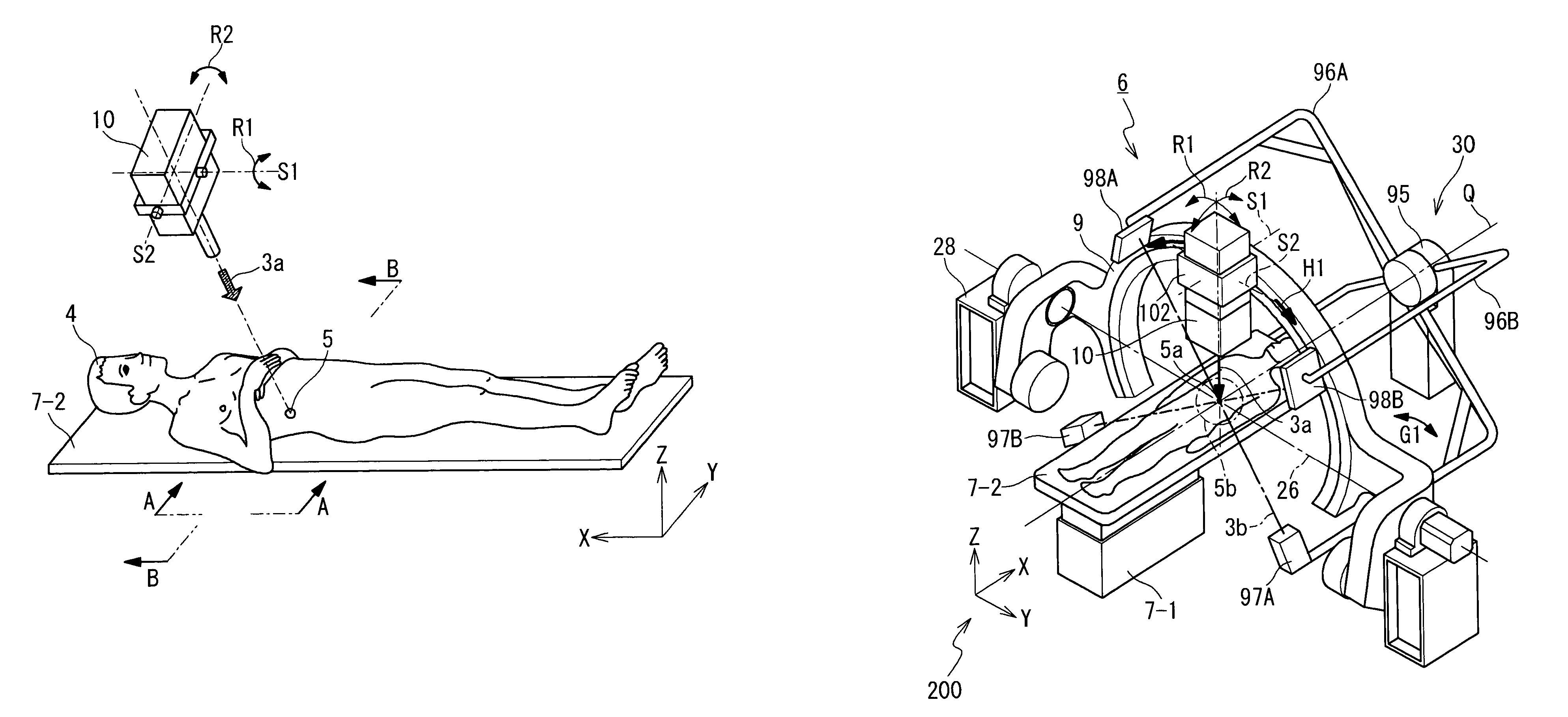
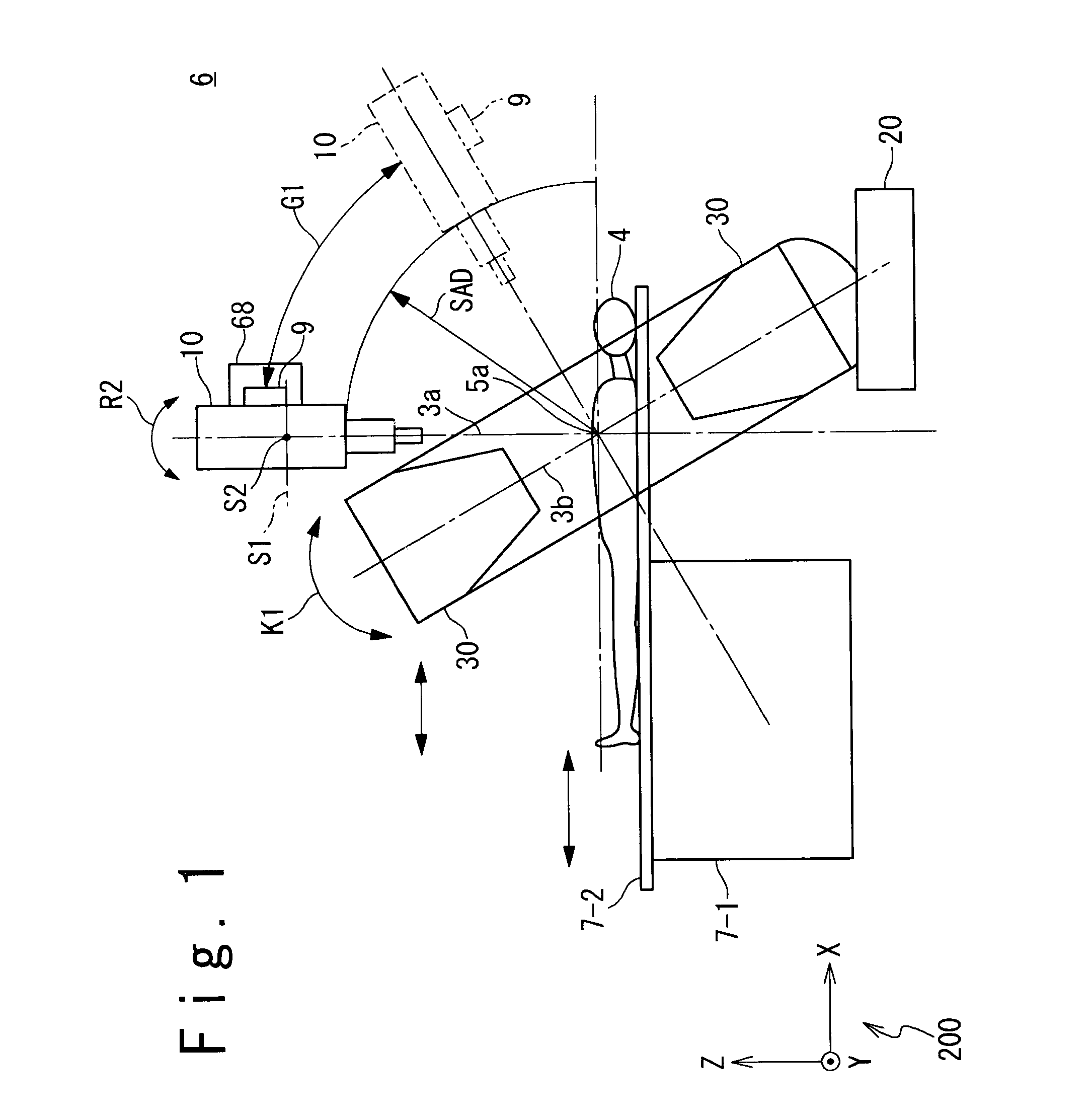
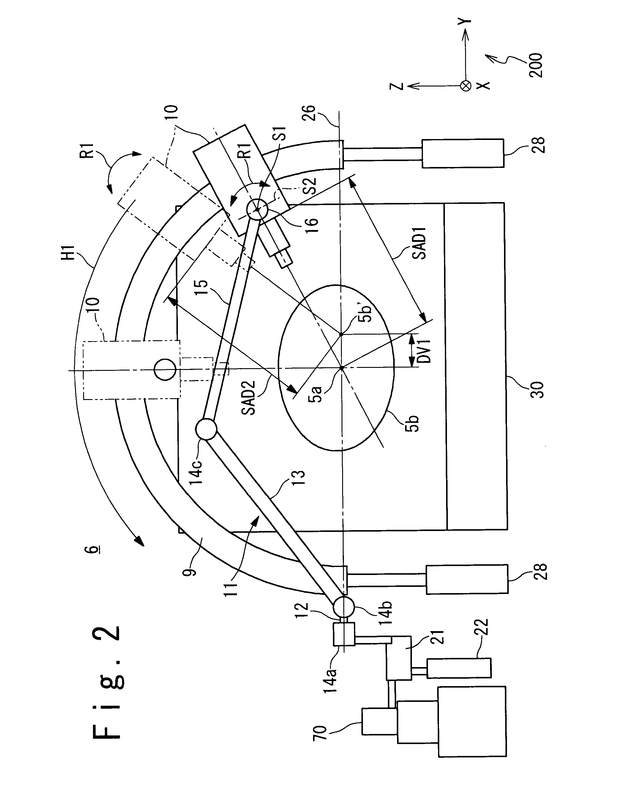
[0088]FIGS. 1 to 3 are a side view, a front view and a perspective view showing the configuration in the first embodiment of the radiotherapy apparatus of the present invention. The parts thereof are omitted depending on the drawing. A coordinate 200 indicates a three-dimensional orthogonal coordinate having an X-axis, a Y-axis and a Z-axis in FIGS. 1 to 3.
[0089]A radiotherapy apparatus 6 includes a treatment bed system 7, an X-ray head 10, a first head swing mechanism 131, a second head swing mechanism 132, an arc guide rail 9, a microwave generating unit 70, a driven type waveguide system 11 and a real time imager 30.
[0090]The treatment bed system 7 has a bed driving system 7-1, a treatment bed 7-2 and a patient immobilization device 7-3.
[0091]The treatment bed 7-2 carries and moves a patient 4 on which radiotherapy is performed. It is put...
second embodiment
[0256]A second embodiment in the radiotherapy apparatus of the present invention will be described below with reference to FIGS. 20, 21. In this embodiment, the explanations of the portions overlapping with those in the first embodiment are omitted.
[0257]FIG. 20 is a side view showing the configuration in the second embodiment of the radiotherapy apparatus of the present invention. And, FIG. 21 is a front view showing a configuration of a rotary drum (a gantry for treatment) in the second embodiment of the radiotherapy apparatus of the present invention.
[0258]In a radiotherapy apparatus 6A in this embodiment, a treatment X-ray head 10, a treatment X-ray source (a CT X-ray tube) 97 and a sensor array 98 are mounted on a rotary drum (treatment gantry) 99. That is, the structure of the entire apparatus is such that the X-ray head 10 is placed on the upper portion of the drum of the X-ray CT inspecting unit of the rotary type, which is the real time imager 30 in the first embodiment. Th...
third embodiment
[0260]A third embodiment of the present invention will be described below with reference to FIG. 22.
[0261]In this embodiment, the explanations of the portions overlapping with those of the first and second embodiments are omitted.
[0262]FIG. 22 is a front view showing the configuration of the rotary drum (the treatment gantry) in the third embodiment of the radiotherapy apparatus of the present invention.
[0263]A radiotherapy apparatus 6B in this embodiment includes the X-ray head 10 for the treatment and two sets of X-ray source 97A or 97B and sensor array 98A or 98B constituting the typical X-ray camera, on the rotational drum (treatment gantry) 99. Those relative positions are fixed within preset ranges. As the preset range, an angle between the sensor array 98B and the isocenter 5a and the X-ray head 10 is 60 to 20 degrees. Preferably, it is 45 to 30 degrees. This is set in accordance with the conditions that they do not have any influence on each other, they are accurately operat...
PUM
 Abstract
Description
Claims
Application Information