
Continuous Extrusion Process for Manufacturing a Z-directed Component for a Printed Circuit Board

a technology of printed circuit board and extrusion process, which is applied in the direction of manufacturing tools, feed-through capacitors, high-frequency circuit adaptations, etc., can solve the problems of difficult to achieve circuit design

Active Publication Date: 2013-05-02
LEXMARK INT INC
View PDF116 Cites 18 Cited by
  • Summary
  • Abstract
  • Description
  • Claims
  • Application Information

AI Technical Summary

Benefits of technology

The patent describes methods for manufacturing Z-directed components for insertion into printed circuit boards. These methods involve simultaneously extruding a plurality of materials to form an extruded object, which is then divided into individual components and cured. The methods also involve varying the timing of extrusion between different sections of the materials to stagger them. Overall, these methods allow for the efficient and reliable production of Z-directed components.

Problems solved by technology

As densities of components for printed circuit boards have increased and higher frequencies of operation are used, some circuits' designs have become very difficult to achieve.

Method used


Image

  • Continuous Extrusion Process for Manufacturing a Z-directed Component for a Printed Circuit Board
  • Continuous Extrusion Process for Manufacturing a Z-directed Component for a Printed Circuit Board
  • Continuous Extrusion Process for Manufacturing a Z-directed Component for a Printed Circuit Board

Examples


Embodiment Construction

[0048]The following description and drawings illustrate embodiments sufficiently to enable those skilled in the art to practice the present invention. It is to be understood that the disclosure is not limited to the details of construction and the arrangement of components set forth in the following description or illustrated in the drawings. The invention is capable of other embodiments and of being practiced or of being carried out in various ways. For example, other embodiments may incorporate structural, chronological, electrical, process, and other changes. Examples merely typify possible variations. Individual components and functions are optional unless explicitly required, and the sequence of operations may vary. Portions and features of some embodiments may be included in or substituted for those of others. The scope of the application encompasses the appended claims and all available equivalents. The following description is, therefore, not to be taken in a limited sense a...


PUM

PropertyMeasurementUnit
Thicknessaaaaaaaaaa
Diameteraaaaaaaaaa
Structureaaaaaaaaaa

Abstract

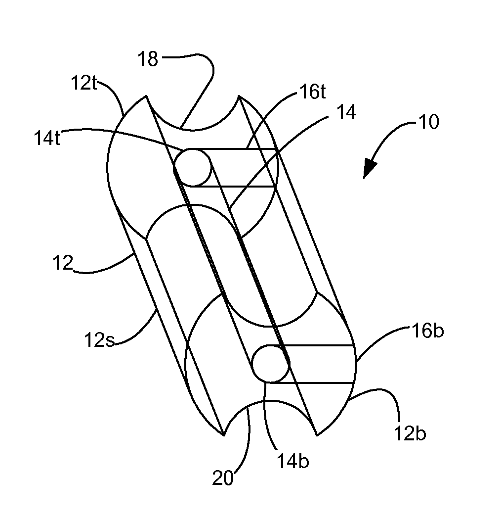
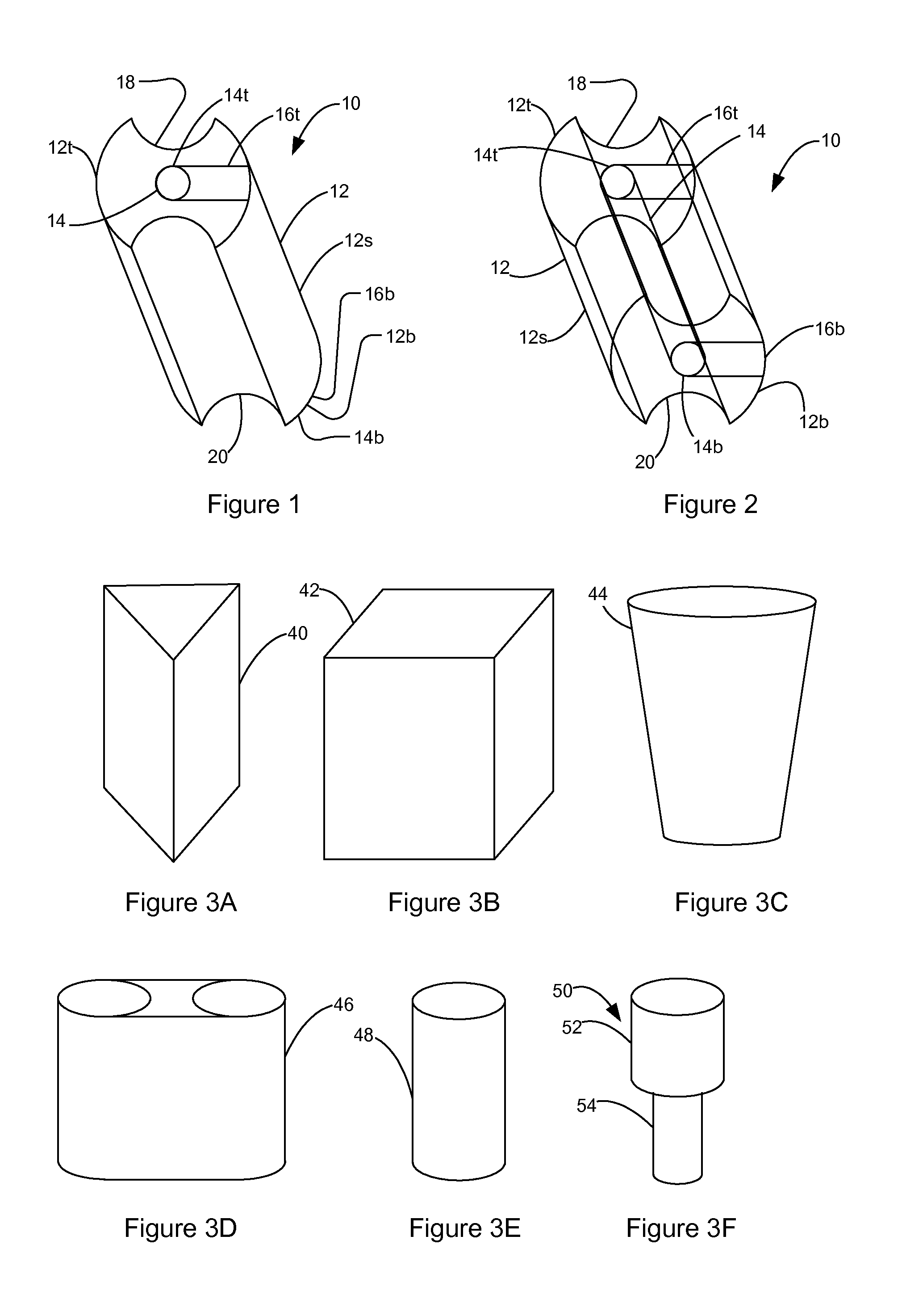
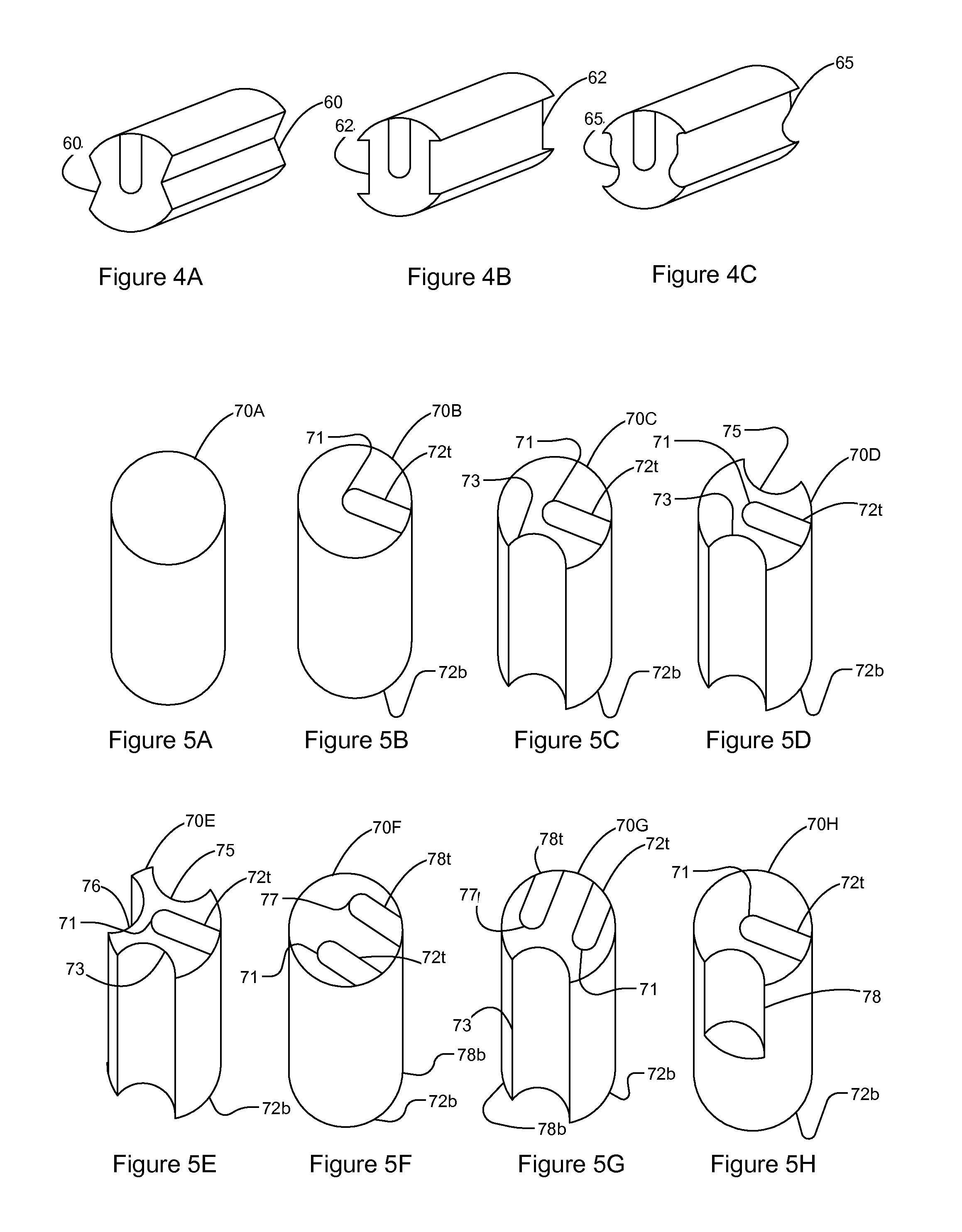
A method for manufacturing a Z-directed component for insertion into a mounting hole in a printed circuit board according to one example embodiment includes simultaneously extruding a plurality of materials according to the structure of the Z-directed component to form an extruded object and forming the Z-directed component from the extruded object. In one embodiment, the extruded object is divided into individual Z-directed components. In one embodiment, the timing of extrusion between predetermined sections of one of the materials is varied in order to stagger the sections in the extruded object.

Description

CROSS REFERENCES TO RELATED APPLICATIONS[0001]This patent application is related to U.S. patent application Ser. No. 13 / 222,748, filed Aug. 31, 2011, entitled “Die Press Process for Manufacturing a Z-Directed Component for a Printed Circuit Board,” U.S. patent application Ser. No. 13 / 222,418, filed Aug. 31, 2011, entitled “Screening Process for Manufacturing a Z-Directed Component for a Printed Circuit Board,” U.S. patent application Ser. No. 13 / 222,376, filed Aug. 31, 2011, entitled “Spin Coat Process for Manufacturing a Z-Directed Component for a Printed Circuit Board,” and U.S. patent application Ser. No. 13 / 250,812, filed Sep. 30, 2011, entitled “Extrusion Process for Manufacturing a Z-Directed Component for a Printed Circuit Board,” which are assigned to the assignee of the present application.BACKGROUND[0002]1. Field of the Disclosure[0003]The present invention relates generally to processes for manufacturing printed circuit board components and more particularly to a continuo...

Claims


Application Information

Patent Timeline
IPC IPC(8): H05K3/30
CPCH01G4/33H01G4/35H05K1/0221H05K1/0231H05K1/0251Y10T29/4913H05K1/184H05K3/4046H05K2201/10053H05K2201/10984H05K1/0298H05K3/306H05K2201/10015Y10T29/49135B29C48/0022B29C48/022B29C48/131H05K3/30B28B3/20B28B11/16B29K2995/0005B29K2995/0007B29L2031/3425
Inventor HARDIN, KEITH BRYANKRATZER, ZACHARY CHARLES NATHANZHANG, QING
Owner LEXMARK INT INC
Learn More