Self-tightening shoe

a shoelace and self-tightening technology, applied in the direction of fastenings, uppers, bootlegs, etc., can solve the problems of arthritis pain or difficulty, velcro closures can become worn, velcro closures can become easily detached,

Active Publication Date: 2013-05-02
PUMA SE
View PDF11 Cites 116 Cited by
  • Summary
  • Abstract
  • Description
  • Claims
  • Application Information

AI Technical Summary

Benefits of technology

[0007]It is a principal object of the present invention to provide a self-tightening shoe which, upon a...

Problems solved by technology

While simple and practical in functionality, such shoelaces need to be tied by hand and often retied as they naturally loosen around the wearer's foot.
Elderly people suffering from arthritis may find it painful or difficult. to pull shoelaces tight and tie knots in order to secure the shoes on their feet.
However, such Velcro c...

Method used


Image

  • Self-tightening shoe
  • Self-tightening shoe
  • Self-tightening shoe

Examples


Embodiment Construction

[0039]The preferred embodiments of the present invention will now foe described with reference to FIGS. 1-7 of the drawings. Identical elements in the various figures are designated with the same reference numerals.

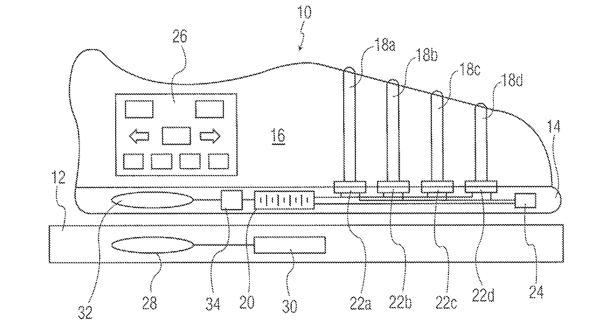
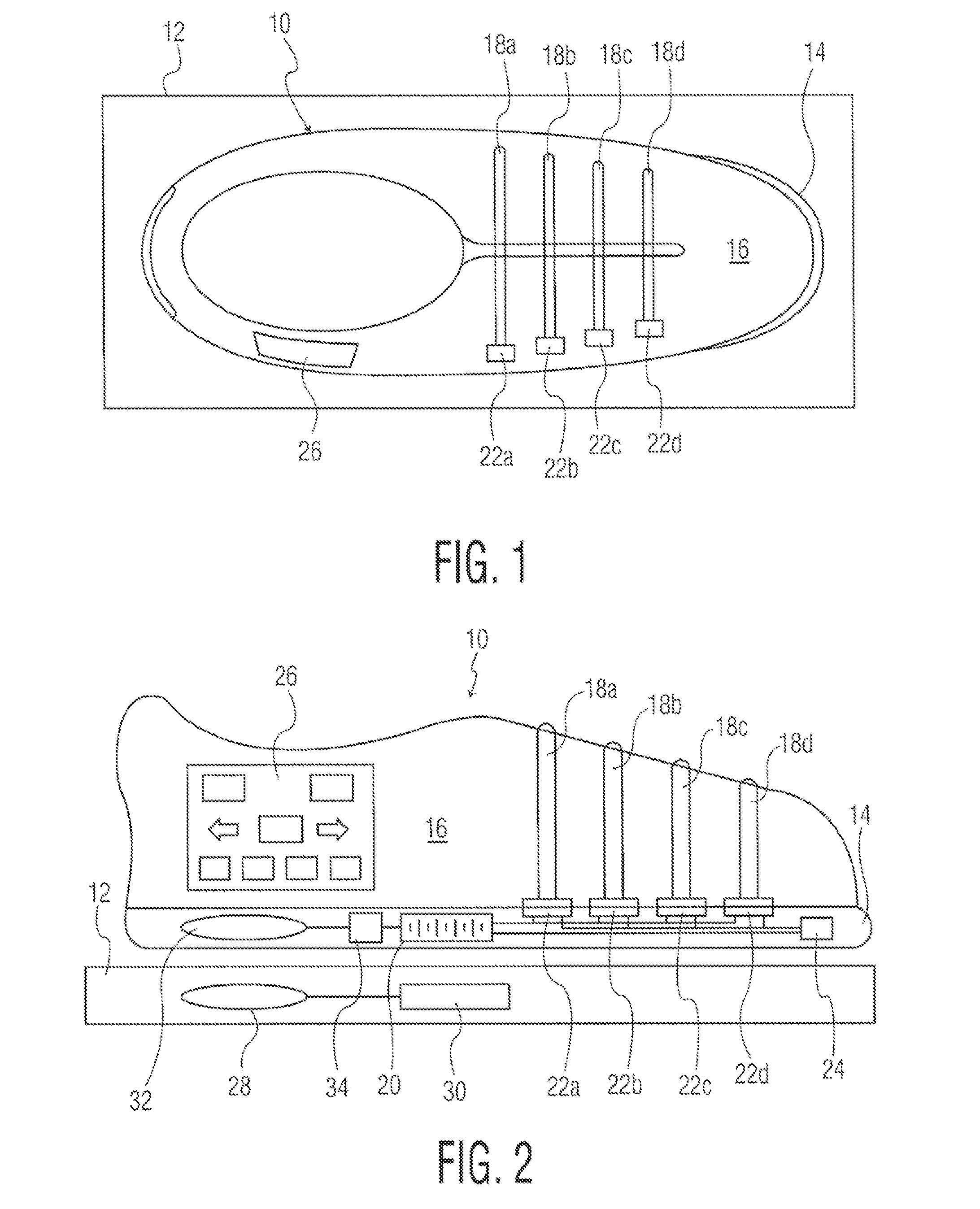
[0040]FIGS. 1 and 2 illustrate a shoe 10 disposed on a charging platform 12, both in top view (FIG. 1) and side view (FIG. 2). The shoe 10 includes a shoe sole 14, a shoe upper 16 affixed to the sole and having a right and left side. A plurality of shoe straps 18a, 18b, 18c and 18d extend from one side of the shoe upper to the other. The shoe further includes a shoe battery 20 and a plurality of shoe tighteners 22a, 22b, 22c and 22d, each coupled to the battery and to one of the shoe straps, for tightening the respective shoe strap in response to a control signal.

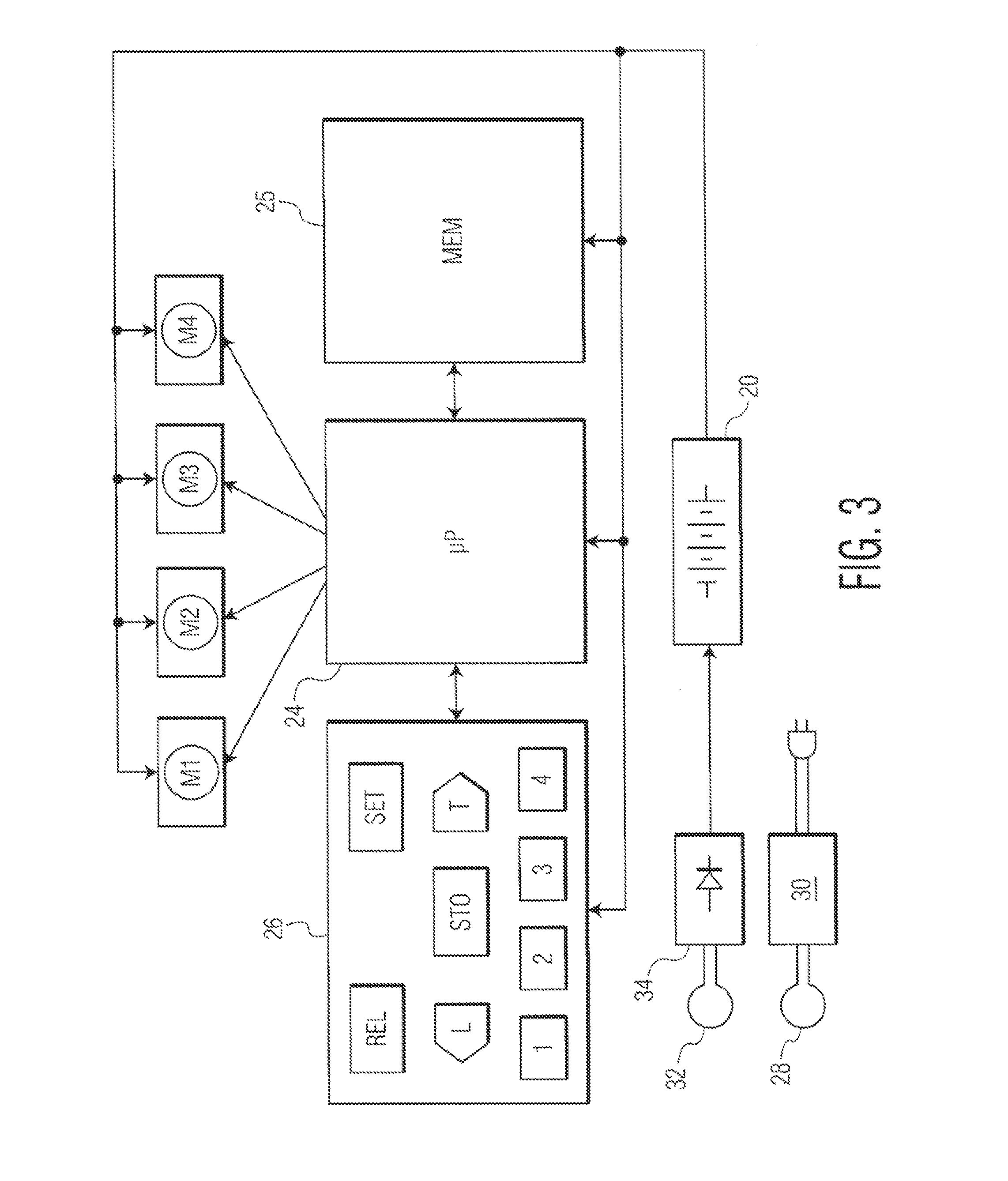
[0041]The control signals, for controlling each strap tightener and thus the tightness of each strap, are received from a logic device 24 embedded in the sole and connected to the battery 20. The logic device, wh...


PUM


Abstract

A show have a sole and a shoe upper is provided with a mechanism for automatically tightening the shoe on a foot to a preset level of tightness that has been stored in memory. The wearer can select and change the level of tightness as desired.

Description

CROSS-REFERENCE TO RELATED APPLICATION[0001]This application claims priority from the U.S. Provisional Application No. 61 / 552,559 filed Oct. 28, 2011.BACKGROUND OF THE INVENTION[0002]The present invention relates to a self-tightening shoe; that is a shoe which can close itself to a desired value of tightness around a foot upon the press of a button.[0003]The term “shoe” is used generically herein to encompass any types of footwear including leather shoes, sneakers, slippers, boots and the like.[0004]The most common form of closure mechanism for a shoe is a lace, criss-crossing between the medial and lateral portions of the shoe upper, that is pulled tight around the instep of the foot and tied in a knot by the wearer. While simple and practical in functionality, such shoelaces need to be tied by hand and often retied as they naturally loosen around the wearer's foot. Young children who have not yet learned to tie a knot require assistance from an attentive parent or caregiver. Elder...

Claims


Application Information

Patent Timeline
IPC IPC(8): A43B23/00
CPCA43B3/0005A43C1/003A43C11/008A43C1/00A43B11/00A43B3/34
Inventor TORRES, GEORGE
Owner PUMA SE
Why Eureka
Try Eureka