Handle switch

Inactive Publication Date: 2013-05-02
HONDA MOTOR CO LTD
View PDF20 Cites 9 Cited by
  • Summary
  • Abstract
  • Description
  • Claims
  • Application Information

AI Technical Summary

Benefits of technology

[0009]It is an object of the present invention to provide a handle switch in which chattering after mounting of the handle switch onto a handlebar can be reduced w

Problems solved by technology

Such a fastening allowance, however, has the following problem.
On the other hand, if the fastening allowa

Method used


Image

  • Handle switch
  • Handle switch
  • Handle switch

Examples


Embodiment Construction

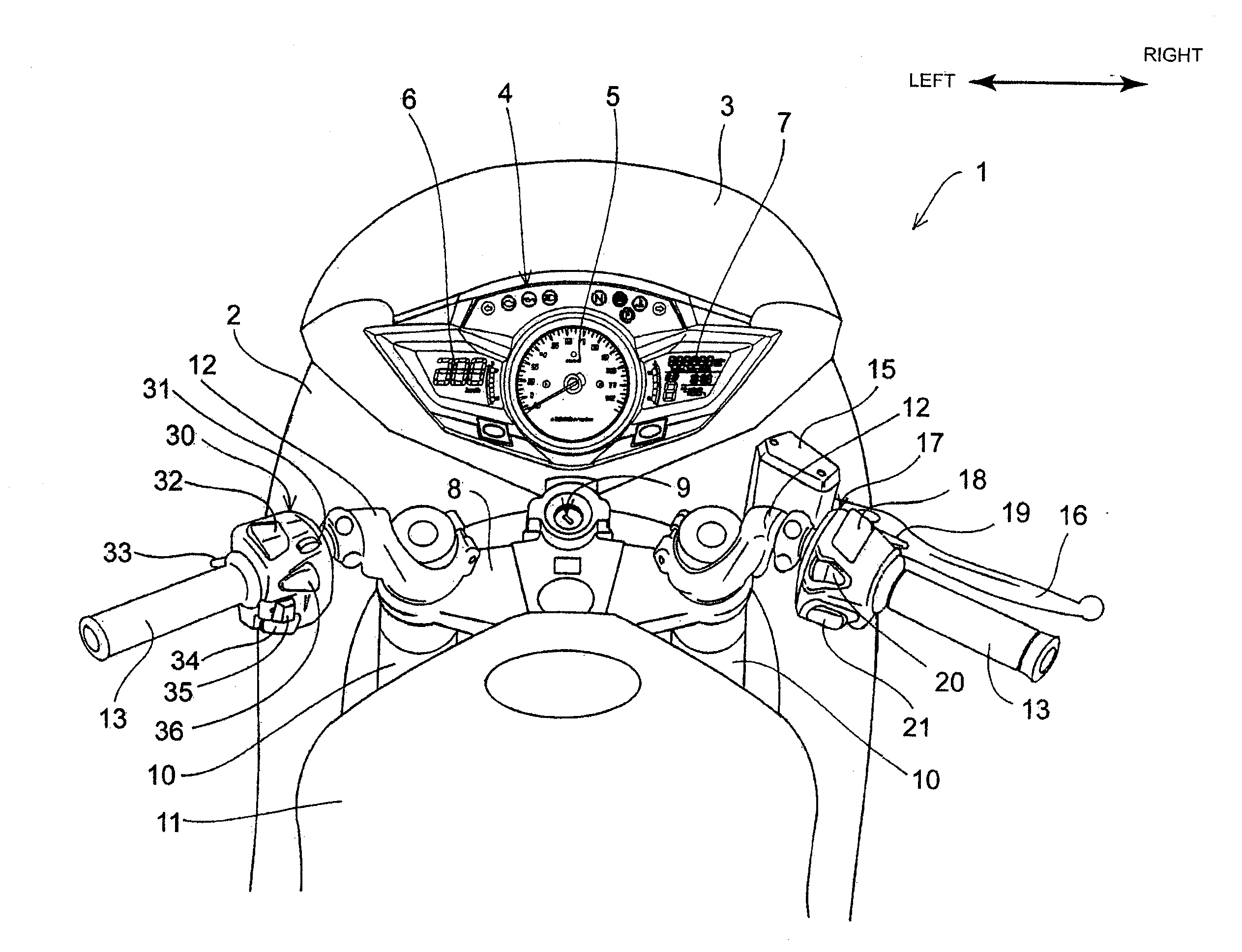
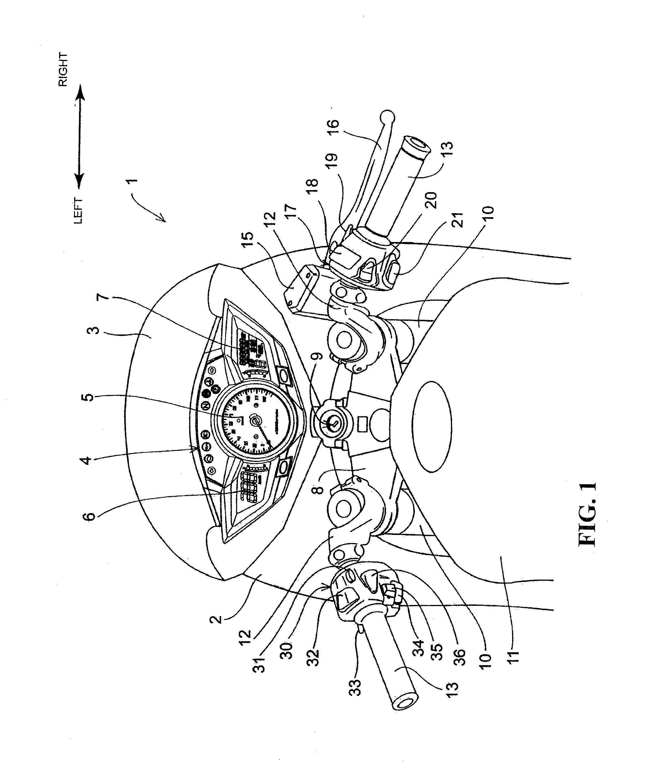
[0035]A preferred embodiment of the present invention will be described in detail below, referring to the drawings. FIG. 1 is an enlarged view of a part of a motorcycle 1 based on application of a handle switch 30 according to one embodiment of the present invention. This view shows a handle and the surroundings thereof as viewed from a rear upper side of the vehicle body, and shows substantially the same state as the state viewed from a driver seated on a seat.

[0036]The vehicle body front side of a steering handle 12 for steering a front wheel (not shown) is covered with a cowling 2. A windscreen 3 is mounted to an upper end portion of the cowling 2. A meter unit 4 having a tachometer 5, a left-side liquid crystal panel 6 for displaying vehicle speed and the like, and a right-side liquid crystal panel 7 having an odometer and the like is disposed on the lower side of the windscreen 3.

[0037]The front wheel of the motorcycle 1 is rotatably supported on lower ends of a pair of left an...


PUM


Abstract

A handle switch wherein chattering after mounting of the handle switch to a handlebar can be restrained while maintaining assembleability of switch cases of bisection structure. The handle switch includes a first case and a second case of bisection structure formed with clamp surfaces making contact with the outer circumference of the handlebar of a motorcycle, the first case and the second case being coupled together, with the handlebar clamped between the clamp surfaces, to thereby fix the handle switch to the handlebar. At least one of the clamp surface formed in the first case and the clamp surface formed in the second case is formed with a rib serving as a fastening allowance in coupling the first case and the second case together. The width B of the rib is set to be smaller than the width A of the clamp surfaces.

Description

CROSS-REFERENCE TO RELATED APPLICATIONS[0001]The present application claims priority under 35 USC 119 to Japanese Patent Application No. 2011-236383 filed Oct. 27, 2011 the entire contents of which are hereby incorporated by reference.BACKGROUND OF THE INVENTION[0002]1. Field of the Invention[0003]The present invention relates to a handle switch, particularly to a handle switch fixed to a handlebar of a motorcycle.[0004]2. Description of Background Art[0005]Hitherto, a handle switch is known wherein a switch case is provided with a plurality of operation switches fixed to a handlebar of a motorcycle, for permitting the rider to operate a horn and turn signal lamps and the like while gripping the handlebar. In many cases, such a handle switch is fastenedly fixed to the handlebar by a method wherein the switch case is designed to be of a bisection structure (composed of two case halves), and the outer circumferential surface of the handlebar is clamped from both sides by the two case ...

Claims


Application Information

Patent Timeline
IPC IPC(8): H01H9/06
CPCB62K23/02B62K11/14
Inventor NAKADA, NAOKIOTA, HIROYASU
Owner HONDA MOTOR CO LTD
Why Eureka
Try Eureka