Electro-Mechanical Three-Way Dual Seat Valve

a three-way dual seat, electromechanical technology, applied in the direction of valve details, valve housings, valve arrangements, etc., can solve the problems of high scrap rate, high pressure on the valve actuator, and wear of the seal surface, so as to reduce or eliminate the leakage of seals and seal wear, the effect of minimizing energy consumption

Inactive Publication Date: 2013-05-02
GM GLOBAL TECH OPERATIONS LLC
View PDF19 Cites 4 Cited by
  • Summary
  • Abstract
  • Description
  • Claims
  • Application Information

AI Technical Summary

Benefits of technology

[0006]The present invention is a three-way dual seat valve which minimizes the seal surface, reduces or eliminates seal leakage and seal wear for the life of the valve, utilizes hydraulic forces innate to the fluid system to minimize energy consumption t

Problems solved by technology

The seals wear due to frictional forces and scrub due to contamination and deposition.
Some of these seals need tight tolerances based on their application which can result in high scrap rates.
In automotive applications, cold coolant and ambient air temperature tends to require high

Method used


Image

  • Electro-Mechanical Three-Way Dual Seat Valve
  • Electro-Mechanical Three-Way Dual Seat Valve
  • Electro-Mechanical Three-Way Dual Seat Valve

Examples


Embodiment Construction

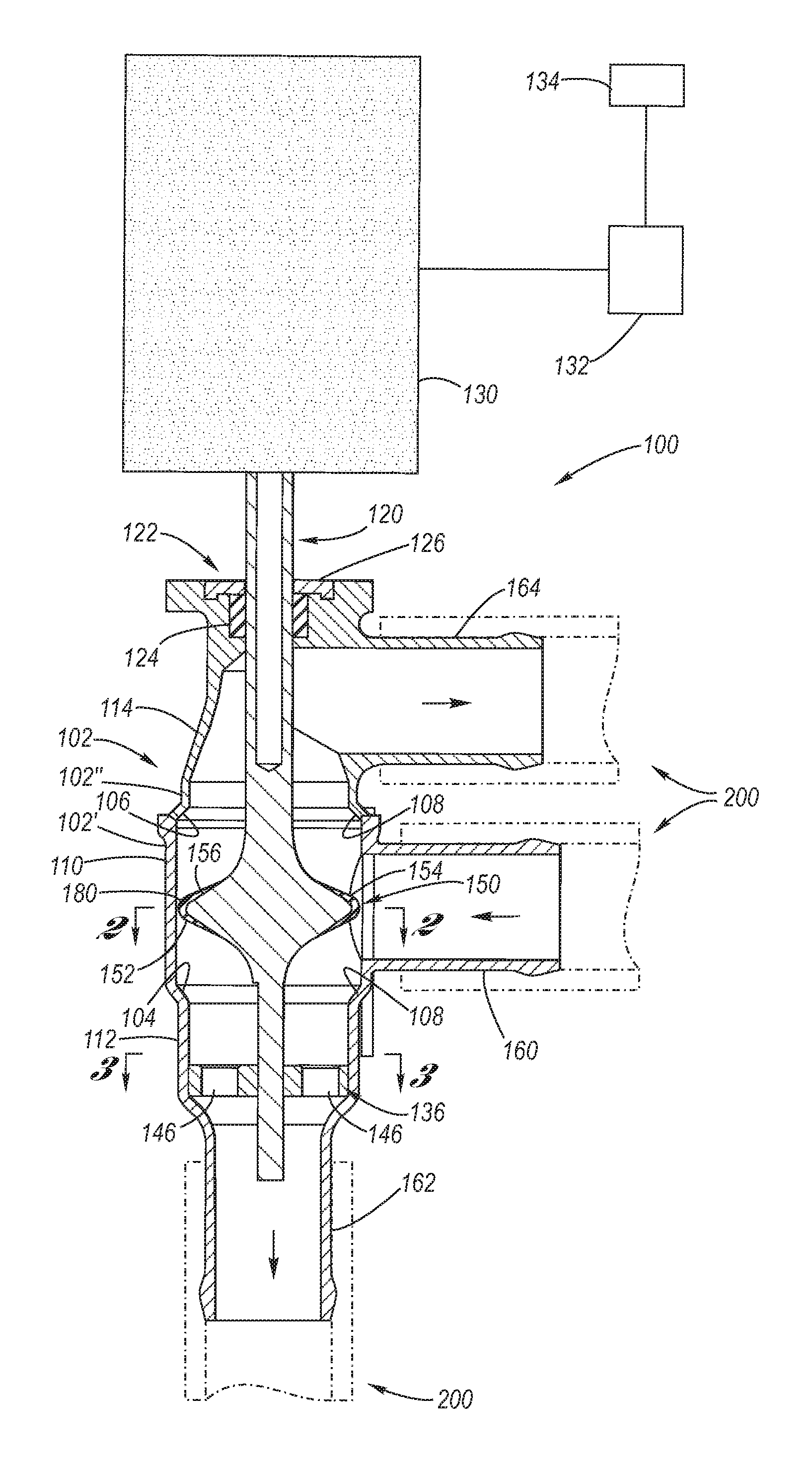
[0024]Referring now to the Drawings, FIGS. 1 through 12 depict various exemplary aspects of the structure and function of a three-way dual seat valve according to the present invention.

[0025]Referring firstly to FIGS. 1 through 9, a three-way dual seat valve 100 according to the present invention will be detailed.

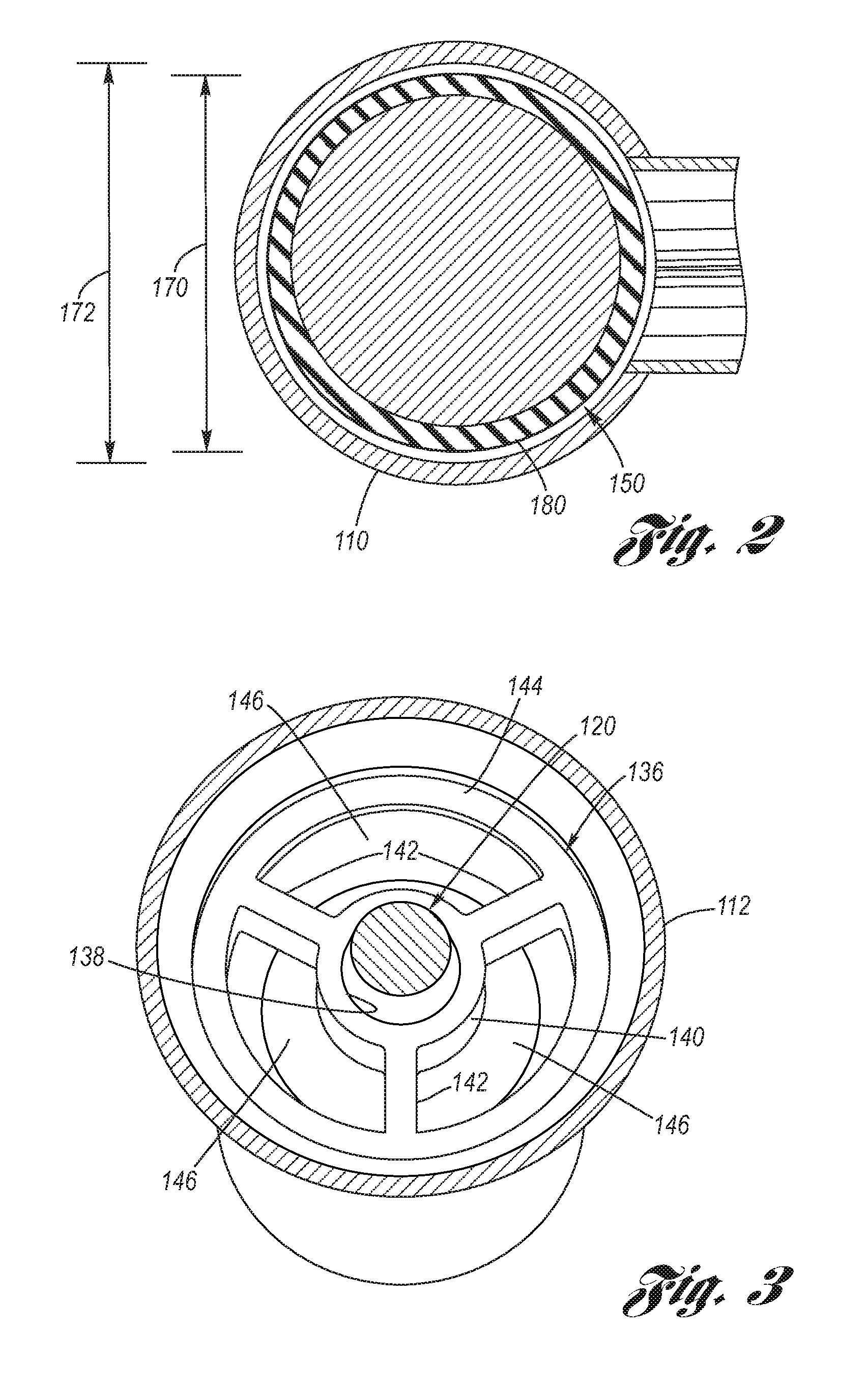
[0026]The three-way dual seat valve according to the present invention includes a valve body 102 which, for purposes of manufacture, is composed of first and second valve body members 102′, 102″ which are mutually welded, threaded or otherwise sealingly joined and mechanically affixed. Within the valve body 102 is a pair of mutually separated annular valve seats, a first valve seat 104 and a second valve seat 106, each being preferably characterized by an annular bevel or taper 108. A medial valve body portion 110 of the valve body 102 is disposed between the first and second valve seats 104, 106. A first distal valve body portion 112 of the valve body 102 is disposed adjoi...


PUM


Abstract

A three-way dual seat valve having a valve body including mutually spaced apart annular first and second valve seats. Reciprocally mounted with respect to the valve body is a valve stem which carries within the valve body an annular, dual-faced valve stem gate. Each gate face thereof is sealingly engageable with a respective valve seat in response to reciprocal movement of the valve stem.

Description

TECHNICAL FIELD[0001]The present invention relates to valves, including coolant valves typically used in automotive applications. More particularly, the present invention relates to a reciprocating, three-way dual seat valve.BACKGROUND OF THE INVENTION[0002]Valves are ubiquitous in fluid flow systems to provide directional control of the fluid flow therewithin. Valves are used to open and close fluid flow directions, wherein the valve may function between a fully open and fully closed state, or may be progressive, wherein the state of opening is selectively somewhere therebetween so as to meter fluid flow. Valves may be two-way, controlling fluid flow with respect to an inlet and an outlet of the valve, or may be three-way, controlling fluid flow with respect to a pair of inlets and a single outlet of the valve or a pair of outlets and a single inlet of the valve.[0003]Valve sealing is important, and common strategy for sealing is with a face seal against a ball, cylinder, or sleeve...

Claims


Application Information

Patent Timeline
IPC IPC(8): F16K3/30
CPCF16K27/0263F16K11/044
Inventor KABEL, KEITH R.
Owner GM GLOBAL TECH OPERATIONS LLC
Why Eureka
Try Eureka