Drive System For An Electro-Mechanical Three-Way Dual Seat Valve

a technology of electro-mechanical and dual seat valves, applied in the direction of multiple way valves, valve details, valve arrangements, etc., can solve the problems of high scrap rate, high pressure on the valve actuator, and wear of the seal surface, so as to reduce or eliminate the leakage and wear of the seal, the effect of minimizing energy consumption

Inactive Publication Date: 2013-05-02
GM GLOBAL TECH OPERATIONS LLC
View PDF21 Cites 10 Cited by
  • Summary
  • Abstract
  • Description
  • Claims
  • Application Information

AI Technical Summary

Benefits of technology

[0007]The present invention is a three-way dual seat valve which minimizes the seal surface, reduces or eliminates seal leakage and seal wear for the life of the valve, utilizes hydraulic forces innate to the fluid system to minimize energy consumption to effect tight sealing, provides a high fluid flow coefficient, has the further ability to meter fluid flow, and has a leadscrew drive system which minimizes over all valve packaging. Accordingly, the three-way dual seat valve with leadscrew drive system of the present invention has a particularly advantageous application to automotive coolant systems.
[0009]The valve stem is reciprocated by operation of a leadscrew drive system, wherein an electric motor rotates a screw which is threadingly engaged with respect to a nut connected with the valve stem, wherein an anti-rotation feature is provided as between the valve stem and the valve body to thereby prevent rotation of the valve stem with respect to the valve body. In response, for example, to electronic programming and sensed data available to an electronic control module, the electric motor is selectively actuated to rotate the screw of the leadscrew clockwise or counterclockwise, whereupon the nut of the leadscrew threads along the screw. Since the nut is connected with the valve body, the valve body is prevented from rotating with the screw, and the screw is non-reciprocally movable with respect to the valve body, rotation of the screw results in reciprocation of the valve stem and the valve stem gate thereof.
[0010]When the valve stem gate is centrally disposed with respect to the inlet, fluid flows to both the first and second outlets, however as the valve stem gate is moved so as to approach one or the other of the valve seats, fluid flow becomes restricted at the approached valve seat to the outlet respectively thereat, whereby proportional fluid flow may be established if the valve stem gate is held separated at a selected separation distance from the approached valve seat. When the valve stem gate is seated at either of the first and second valve seats, the engaging gate face thereof sealingly abuts the valve seat, assisted by hydraulic pressure (when present) of the fluid, whereby fluid flow is prevented from passing through the now closed valve seat and only passes through the other, open, valve seat and its respective outlet. Upon movement of the valve stem in the opposite direction, the sealing of the other valve seat is effected by sealing abutment with the other gate face of the valve stem gate, and fluid flow is then possible only through the respectively other of the outlets.
[0011]As the gate face of the valve stem gate separates from its respective valve seat fluid flow therepast will be relatively rapid, depending upon fluid pressure, due to the small annular separation distance between the valve seat and the valve stem gate, whereby any debris disposed thereat will be flushed away by the rushing fluid.
[0012]Accordingly, it is an object of the present invention to provide a three-way dual seat valve which minimizes the seal surface, reduces or eliminates seal leakage and seal wear for the life of the valve, utilizes hydraulic forces innate to the fluid system to minimize energy consumption during operation of the valve, provides a high fluid flow coefficient, and has the further ability to meter fluid flow.

Problems solved by technology

The seals wear due to frictional forces and scrub due to contamination and deposition.
Some of these seals need tight tolerances based on their application which can result in high scrap rates.
In automotive applications, cold coolant and ambient air temperature tends to require high forces to actuate the valve.
Short life and premature leakage are the major issues on this style of valve.
Needle and seat solenoid valves have high pressure drops and excessive energy consumption.
Pressure drop and energy consumption are the major detriments with this style of valve.

Method used


Image

  • Drive System For An Electro-Mechanical Three-Way Dual Seat Valve
  • Drive System For An Electro-Mechanical Three-Way Dual Seat Valve
  • Drive System For An Electro-Mechanical Three-Way Dual Seat Valve

Examples


Embodiment Construction

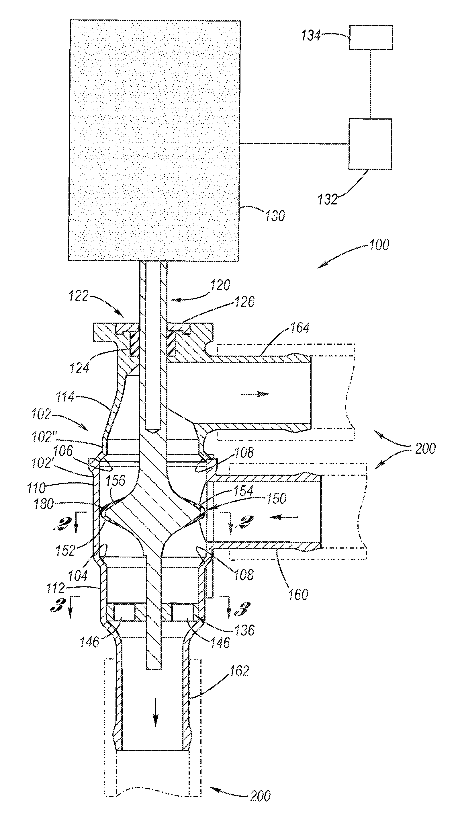
[0035]Referring now to the Drawings, FIGS. 1 through 12 depict various exemplary aspects of the structure and function of a three-way dual seat valve, and FIGS. 13 through 21 depict various exemplary aspects of a leadscrew drive system according to the present invention for the three-way dual seat valve.

[0036]Referring firstly to FIGS. 1 through 12, a three-way dual seat valve 100 will now be detailed. This three-way dual set valve 100 is described in U.S. patent application Ser. No. 13 / 286,452, filed on Nov. 1, 2011, to K. R. Kabel, entitled “Electro-Mechanical Three-Way Dual Seat Valve”, and assigned to the assignee hereof, wherein the disclosure of said application is hereby incorporated herein by reference.

[0037]The three-way dual seat valve according to the present invention includes a valve body 102 which, for purposes of manufacture, is composed of first and second valve body members 102′, 102″ which are mutually welded, threaded or otherwise sealingly joined and mechanically...


PUM


Abstract

A three-way dual seat valve having a valve body including mutually spaced apart annular first and second valve seats. Reciprocally mounted with respect to the valve body is a dual-faced valve stem gate, wherein each gate face thereof is sealingly engageable with a respective valve seat in response to reciprocal movement of the valve stem gate effected via a leadscrew drive system.

Description

CROSS-REFERENCE TO RELATED APPLICATIONS[0001]The present application is a continuation-in-part application of Ser. No. 13 / 286,452, filed on Nov. 1, 2011, and which is presently pending.TECHNICAL FIELD[0002]The present invention relates to valves, including coolant valves typically used in automotive applications. More particularly, the present invention relates to a reciprocating, three-way dual seat valve. Still more particularly, the present invention relates to a leadscrew drive system for providing actuation of the valve.BACKGROUND OF THE INVENTION[0003]Valves are ubiquitous in fluid flow systems to provide directional control of the fluid flow therewithin. Valves are used to open and close fluid flow directions, wherein the valve may function between a fully open and fully closed state, or may be progressive, wherein the state of opening is selectively somewhere therebetween so as to meter fluid flow. Valves may be two-way, controlling fluid flow with respect to an inlet and an...

Claims


Application Information

Patent Timeline
Patent Type & Authority Applications(United States)
IPC IPC(8): F16K3/00
CPCF16K11/044F16K31/508
Inventor KABEL, KEITH R.SHAMPINE, SCOTT F.PAREKH, BIPIN D.
Owner GM GLOBAL TECH OPERATIONS LLC
Why Eureka
Try Eureka