Inertial sensor aided stationary object detection in videos

Inactive Publication Date: 2013-05-02
QUALCOMM INC
View PDF6 Cites 15 Cited by
  • Summary
  • Abstract
  • Description
  • Claims
  • Application Information

AI Technical Summary

Benefits of technology

[0007]Some regions of the image may show strong similarity between the inertial sensor estimated image shift and the image shift calculated by known image processing techniques. The portions of the image may be defined as sub-frames of the image or individual fine grained features identified and described by using known techniques such as scale invarian

Problems solved by technology

A common problem in video analysis is to differentiate a stationary object from moving objects.
However, many of these techniques suffer from an inherent limitation of relying on the size of the

Method used


Image

  • Inertial sensor aided stationary object detection in videos
  • Inertial sensor aided stationary object detection in videos
  • Inertial sensor aided stationary object detection in videos

Examples


Embodiment Construction

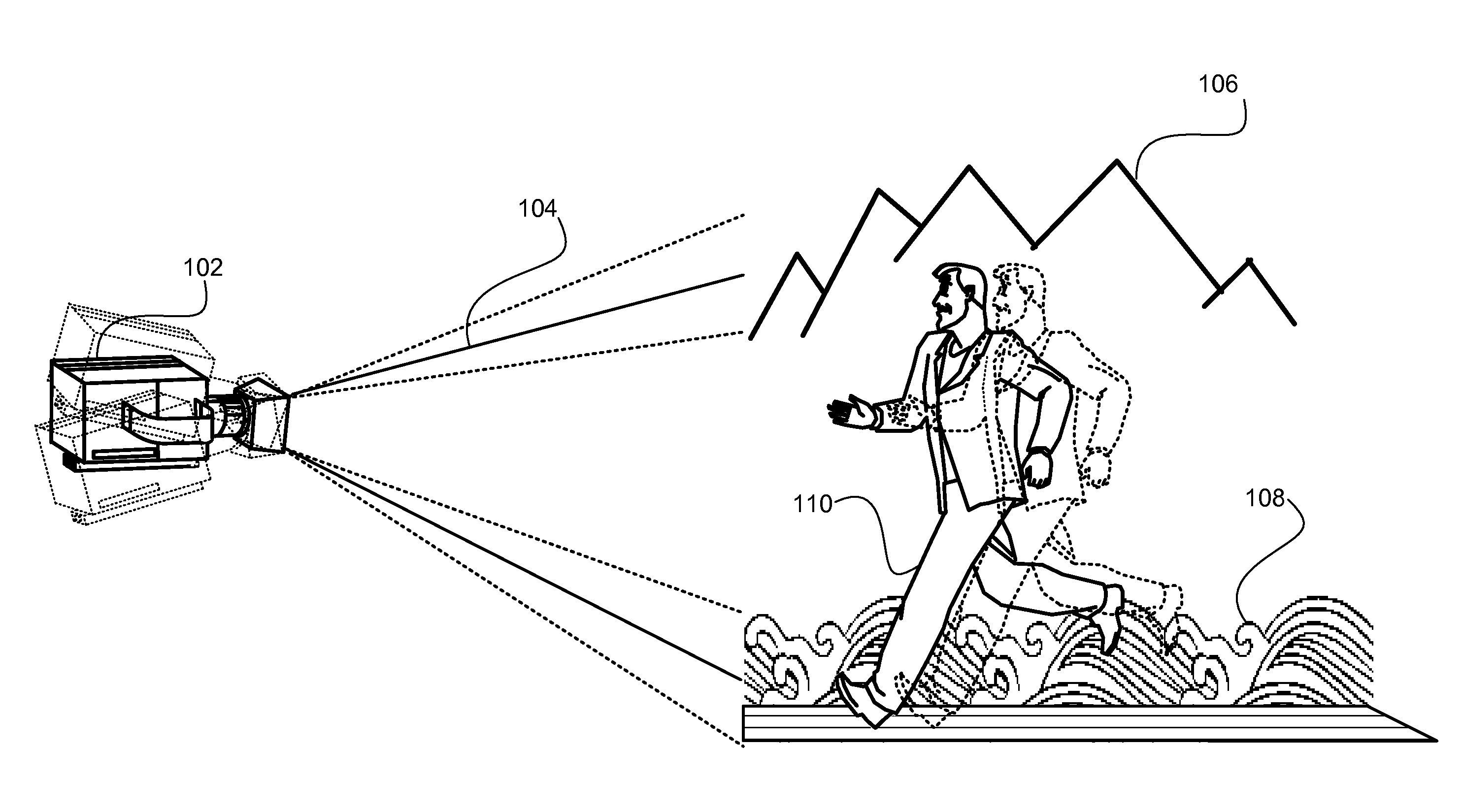
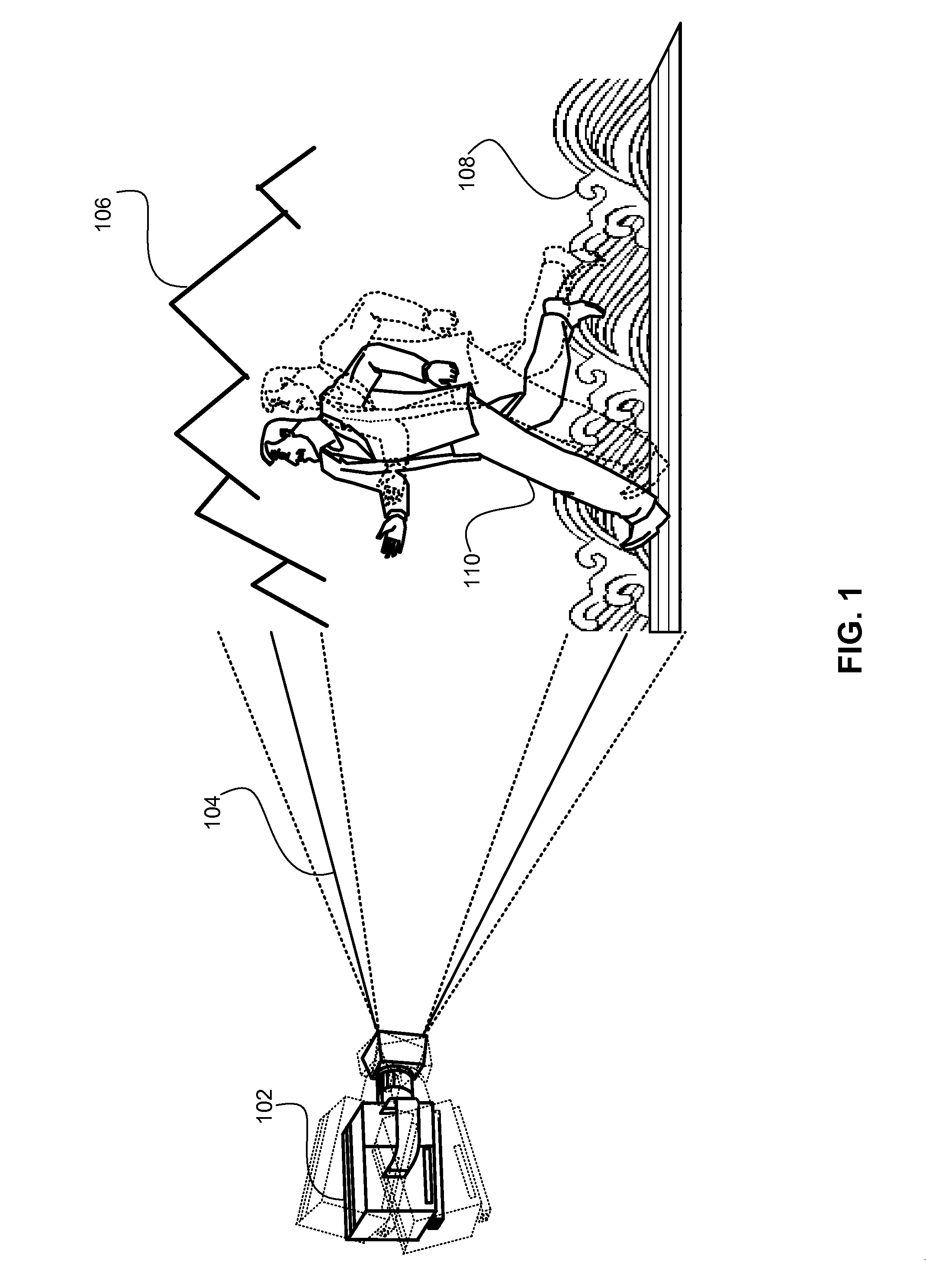
[0034]A common problem in video analysis is to differentiate a stationary object from moving objects (usually in the foreground). Competent video analysis relies on the ability to differentiate stationary objects (e.g., background object) from moving objects. Numerous techniques exist to perform background subtraction based on image processing algorithms. However, many of these techniques suffer from an inherent limitation of relying on the size of the moving object being small in comparison to the complete image. This may provide erroneous results where the moving object is much larger that the stationary object.

[0035]Accordingly, a technique for stationary object detection in a video provided herein utilizes inertial sensor information for improved stationary object detection. Gyroscopes, accelerometers and magnetometers are examples of such inertial sensors. Inertial sensors provide a good measure for the movement of the camera. This includes movements caused by panning as well a...


PUM


Abstract

Techniques described herein may provide a method for improved stationary object detection utilizing inertial sensor information. Gyroscopes and accelerometers are examples of such inertial sensors. The movement of the camera causes shifts in the image captured. Image processing techniques may be used to track the shift in the image on a frame-by-frame basis. The movement of the camera may be tracked using inertial sensors. By calculating the degree of similarity between the image shift as predicted by image processing techniques with motion of the device estimated using an inertial sensor, the device can estimate the portions of the image that are stationary and those that are moving.

Description


Claims


Application Information

Patent Timeline
Owner QUALCOMM INC
Why Eureka
Try Eureka