Patient positioning support structure

a positioning support and patient technology, applied in the field of patient positioning support structures, can solve the problems of base members, obstructing the movement of c-arm and o-arm mobile fluoroscopic imaging devices, and unsatisfactory cantilevered patient support structures

Active Publication Date: 2013-05-09
WARSAW ORTHOPEDIC INC
View PDF22 Cites 136 Cited by
  • Summary
  • Abstract
  • Description
  • Claims
  • Application Information

AI Technical Summary

Benefits of technology

[0013]The present disclosure is directed to a patient positioning support structure that permits adjustable positioning, repositioning and selectively lockable support of a patient's head and upper body, lower body and limbs in up to a plurality of individual planes while permitting rolling or tilting, angulation or bending and

Problems solved by technology

However, existing cantilevered patient support structures are unsatisfactory, incorporating either a massive base to counterbalance the extended support member or a large overhead frame structure to provide support from above.
The enlarged base members associated with such cantilever designs are problematic in that they can and do obstruct the movement of C-arm and O-arm mobile fluoroscopic imaging devices and other equipment.
Surgical tables with overhead frame structures are bulky and may require the use of dedicated operating rooms, since in some cases they cannot be moved easily out of the way.
Neither of these desi

Method used


Image

  • Patient positioning support structure
  • Patient positioning support structure
  • Patient positioning support structure

Examples


Embodiment Construction

[0036]As required, detailed embodiments of the patient positioning support structure are disclosed herein; however, it is to be understood that the disclosed embodiments are merely exemplary of the apparatus, which may be embodied in various forms. Therefore, specific structural and functional details disclosed herein are not to be interpreted as limiting, but merely as a basis for the claims and as a representative basis for teaching one skilled in the art to variously employ the disclosure in virtually any appropriately detailed structure.

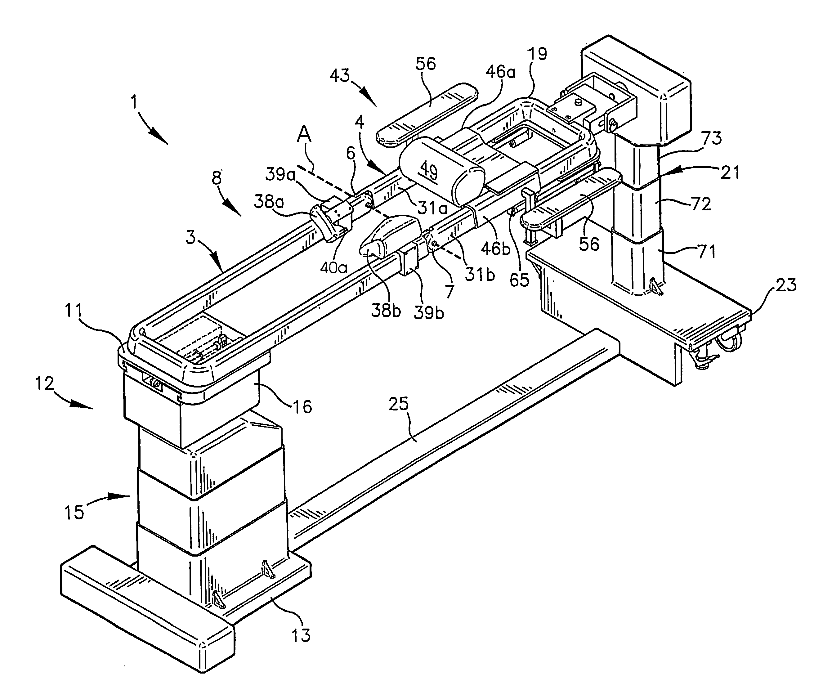
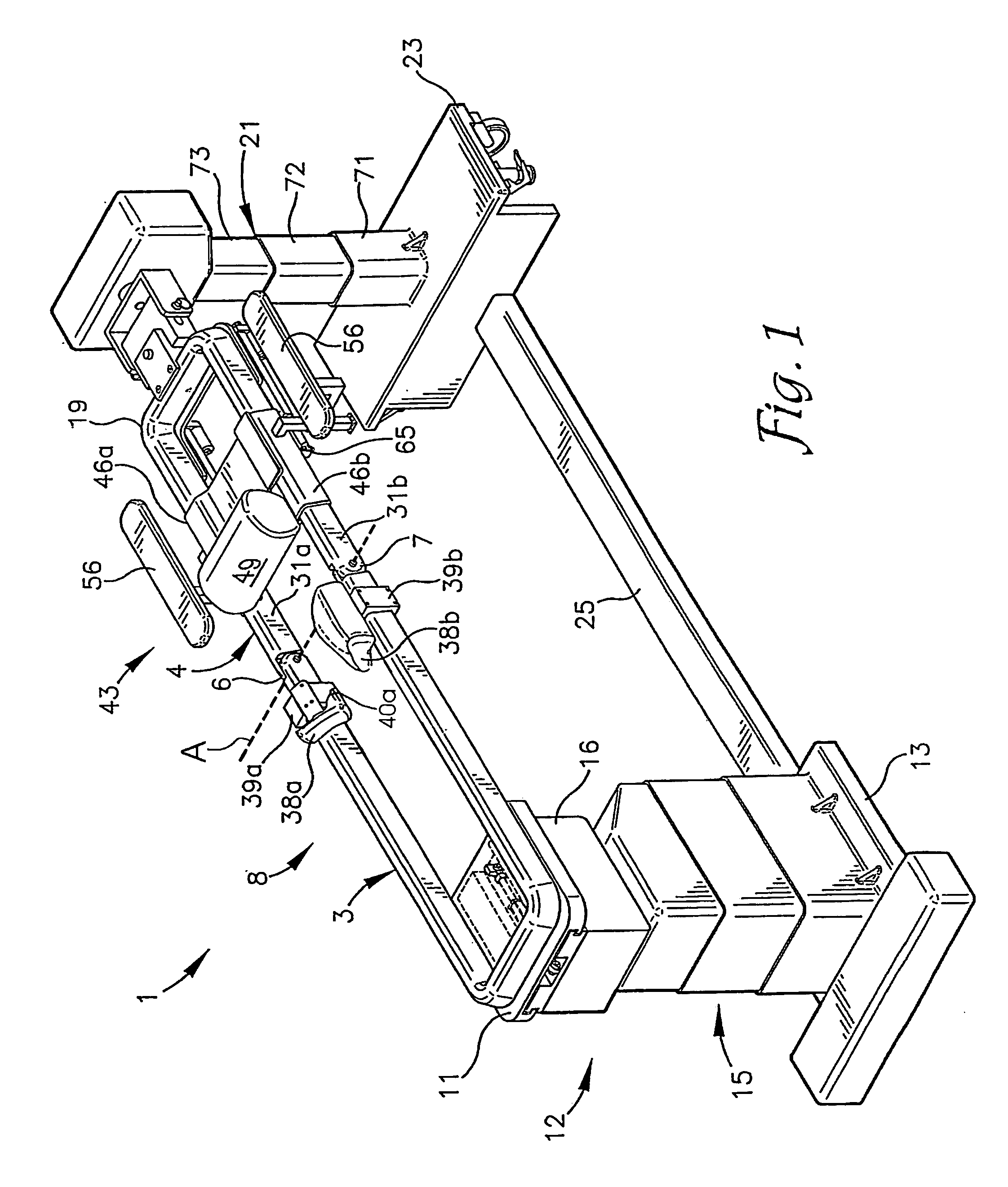
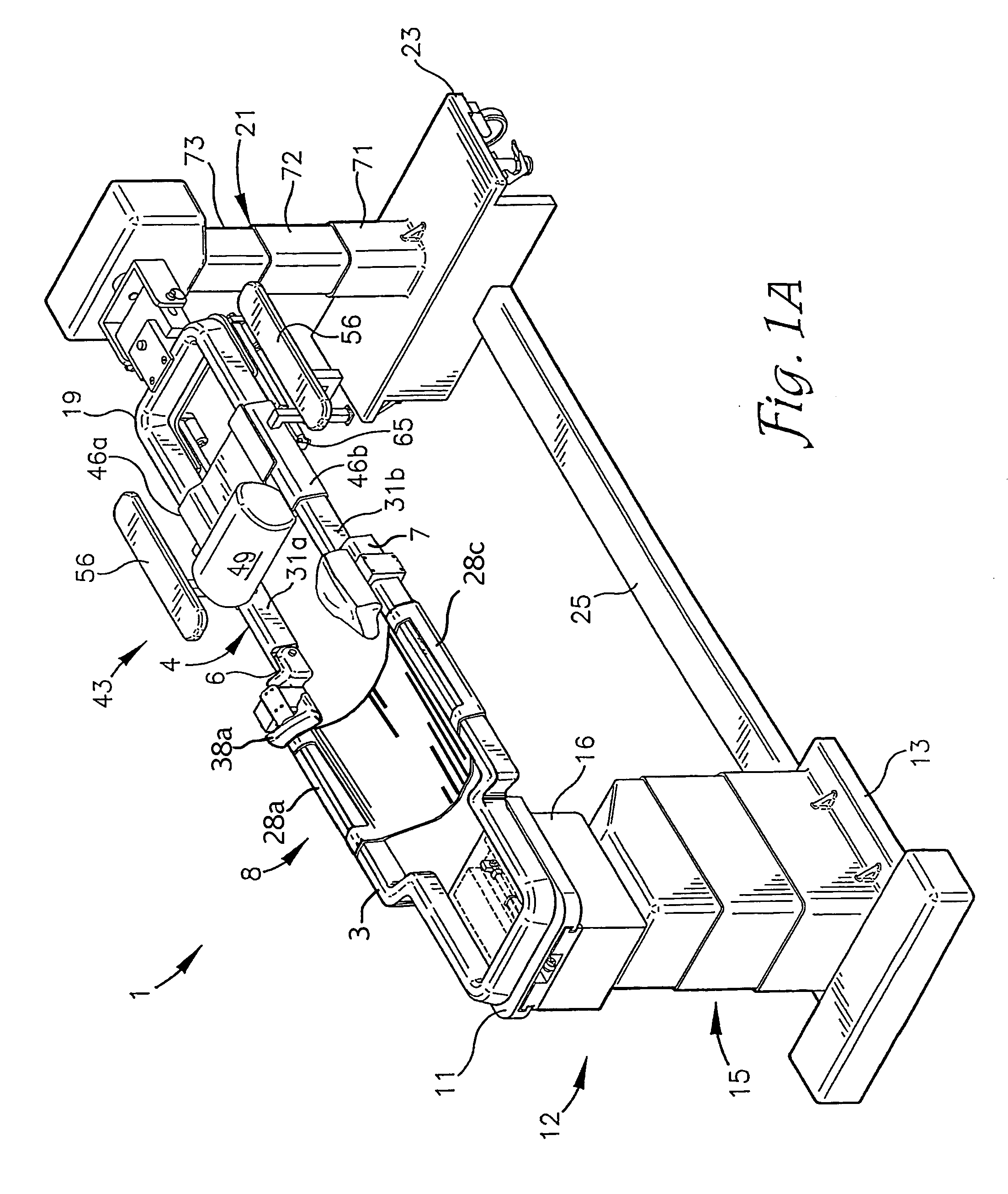
[0037]Referring now to the drawings, an embodiment of a patient positioning and support assembly, table or system according to the disclosure is generally designated by the reference numeral 1 and is depicted in FIGS. 1-12. The assembly 1 includes first and second patient support sections, frames or structures 3 and 4 connected together by spaced apart opposed hinges 6 and 7 to form an articulated patient support or patient support framework 8. T...


PUM


Abstract

An articulating patient support table comprises first and second patient support sections hingedly connected together along respective hinge ends. A longitudinal translation subassembly connected to a base by a position adjustable pedestal supports the first patient support section in cantilevered relationship. The position adjustment assembly includes a lift mechanism operable to raise and lower the longitudinal translation subassembly relative to the base and a pivot assembly operable to pivot the longitudinal translation subassembly fore and aft and side to side relative to the base.

Description

CROSS-REFERENCE TO RELATED APPLICATIONS[0001]This application claims the benefit of U.S. Provisional Application No. 61 / 627,752, which was filed Oct. 17, 2011, and which is incorporated by reference herein.BACKGROUND OF THE INVENTION[0002]The present disclosure is broadly concerned with structure for use in supporting and maintaining a patient in a desired position during examination and treatment, including medical procedures such as imaging, surgery and the like. More particularly, it is concerned with structure having patient supports that can be adjusted to allow a surgeon to selectively position the patient for convenient access to the surgical field and provide for manipulation of the patient during surgery including the tilting, angulation or bending of a trunk and / or a joint of a patient while in a generally supine, prone or lateral position. It is also concerned with structure for adjusting and / or maintaining the spatial relation between the inboard ends of the patient supp...

Claims


Application Information

Patent Timeline
IPC IPC(8): A61G13/04
CPCA61G13/0036A61G13/02A61G13/04A61G2013/0054A61G13/08A61G2203/12A61G13/06A61G13/0054
Inventor JACKSON, ROGER P.
Owner WARSAW ORTHOPEDIC INC
Why Eureka
Try Eureka