Endotracheal tube with dual port subglottic secretion suctioning

a technology of subglottic secretion and endotracheal tube, which is applied in the direction of suction devices, pump control, other medical devices, etc., can solve the problems of traumatic re-intubation of the patient's trachea and unusable subglottic secretions to coll

Inactive Publication Date: 2013-05-09
TELEFLEX MEDICAL INC
View PDF6 Cites 16 Cited by
  • Summary
  • Abstract
  • Description
  • Claims
  • Application Information

AI Technical Summary

Benefits of technology

The present invention provides an endotracheal tube that can overcome the problems of the prior art to some extent. This helps to improve the performance of the device and make it more effective in its use.

Problems solved by technology

The technical problem addressed in this patent text is the need to remove subglottic secretions without having to remove the endotracheal tube, in order to prevent ventilator-associated pneumonia (VAP) in patients. Current methods of removing these secretions, such as re-intubation or suction, are not ideal. The patent aims to provide a device and method for suctioning these secretions without the need for tube removal.

Method used


Image

  • Endotracheal tube with dual port subglottic secretion suctioning
  • Endotracheal tube with dual port subglottic secretion suctioning
  • Endotracheal tube with dual port subglottic secretion suctioning

Examples


Embodiment Construction

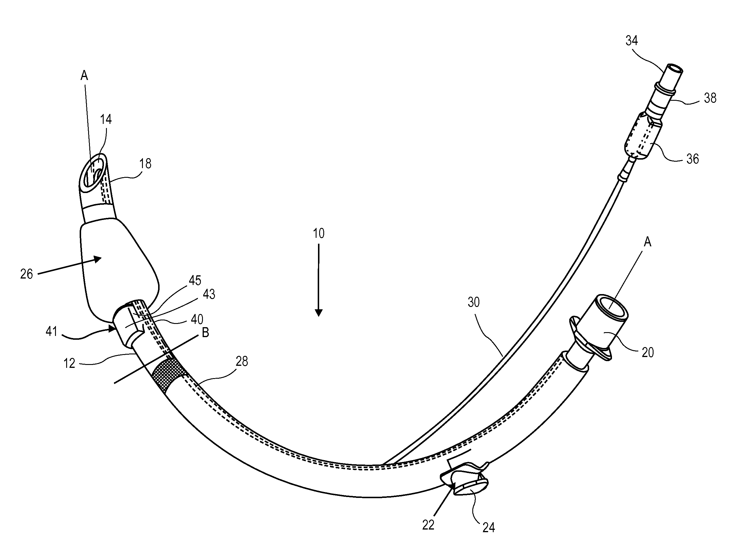
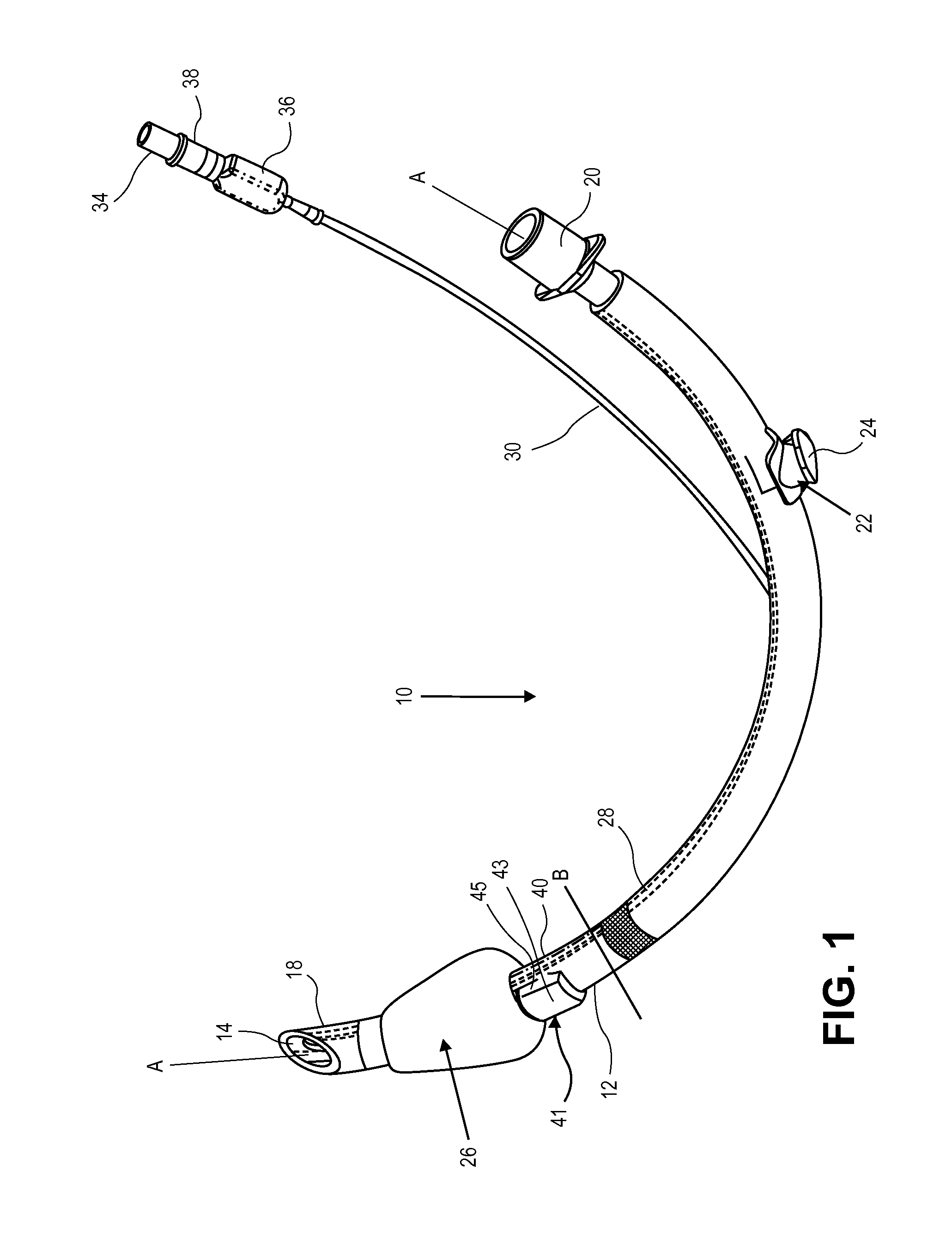
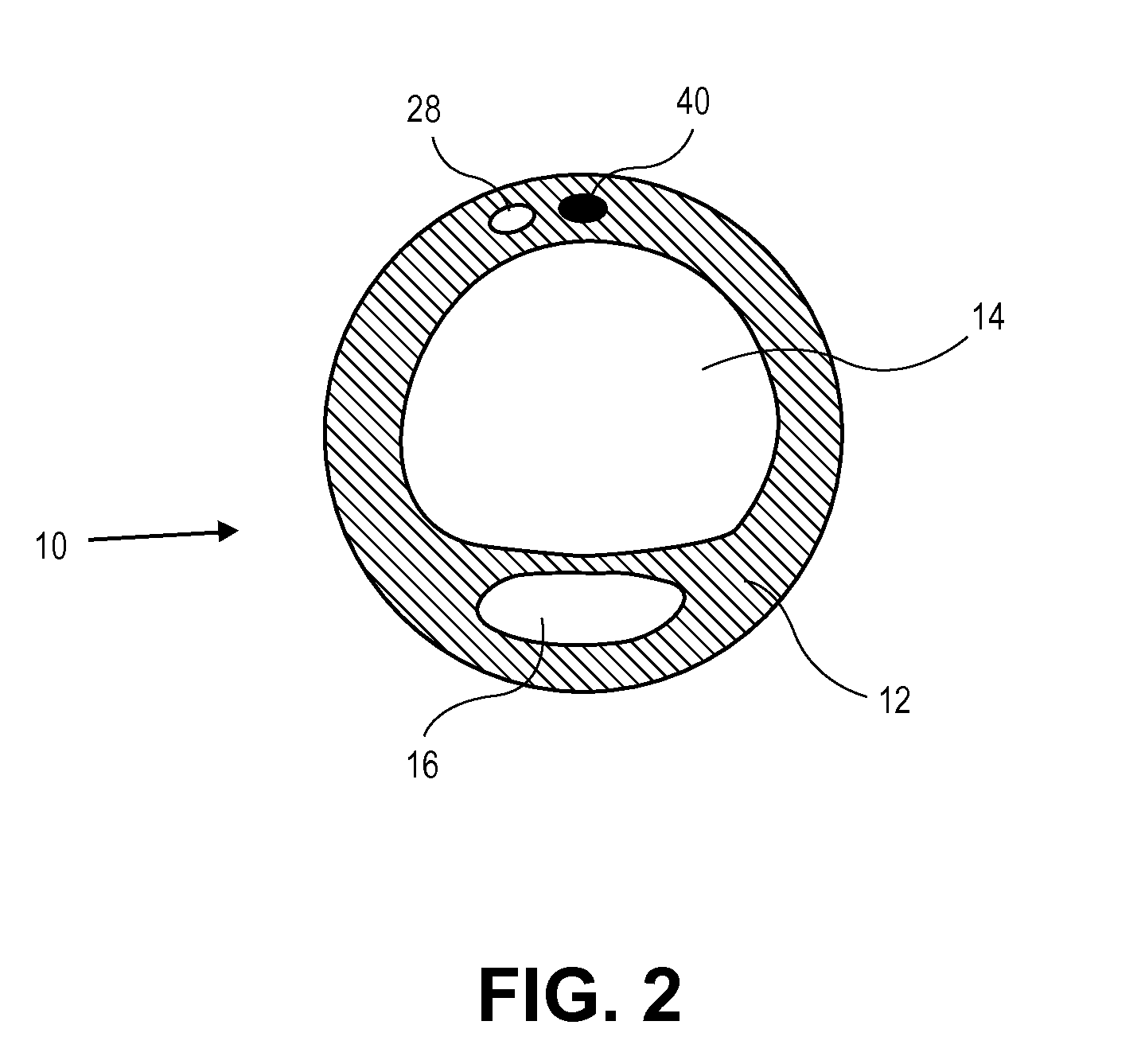
[0037]The present invention provides in some embodiments, an endotracheal tube with dual port subglottic secretion suction. The endotracheal tube is an elongate tube having an outer wall defining an elongate central lumen and an elongate suction lumen. An inflatable cuff is attached near a distal end of the elongate tube. The suction lumen terminates in a suction opening near a distal end of the endotracheal tube. The wall of the endotracheal tube defines the suction opening, such that it includes a dual port configuration.

[0038]The invention will now be described with reference to the drawing figures, in which like reference numerals refer to like parts throughout. FIG. 1 illustrates an endotracheal tube 10 in accordance with the invention. The endotracheal tube 10 includes an outer wall 12 which defines a generally cylindrical central lumen 14. The outer wall 12 also defines an elongate suction lumen 16. The endotracheal tube 10 has a longitudinal axis “A” extending through the le...


PUM


Abstract

The present invention provides in some embodiments, an endotracheal tube with subglottic secretion suction and a detachable suction line. The endotracheal tube is an elongate tube having an outer wall defining an elongate central lumen and an elongate suction lumen. The outer wall also defines an opening to the suction lumen near a distal end of the endotracheal tube An inflatable cuff is attached near a distal end of the elongate tube. The shoulder of the inflatable cuff is inverted in order to increase the diameter of the cuff from its distal end to its proximal end. A diffuser cap is positioned over the opening to the suction lumen and defines a fluid flow path for secretions into the suction lumen through the opening to the suction lumen.

Description


Claims


Application Information

Patent Timeline
Owner TELEFLEX MEDICAL INC
Why Eureka
Try Eureka