Method of defrosting an energy recovery ventilator unit

a ventilator unit and energy recovery technology, applied in the field of space conditioning systems, can solve problems such as reducing the functionality of the uni

Inactive Publication Date: 2013-05-16
LENNOX IND
View PDF21 Cites 35 Cited by
  • Summary
  • Abstract
  • Description
  • Claims
  • Application Information

AI Technical Summary

Benefits of technology

[0005]Another embodiment is an energy recovery ventilator unit. The energy recovery ventilator unit comprises a defro

Problems solved by technology

Sometimes the energy recovery ventilator unit can become

Method used


Image

  • Method of defrosting an energy recovery ventilator unit
  • Method of defrosting an energy recovery ventilator unit
  • Method of defrosting an energy recovery ventilator unit

Examples


Embodiment Construction

[0013]The term, “or,” as used herein, refers to a non-exclusive or, unless otherwise indicated. Also, the various embodiments described herein are not necessarily mutually exclusive, as some embodiments can be combined with one or more other embodiments to form new embodiments.

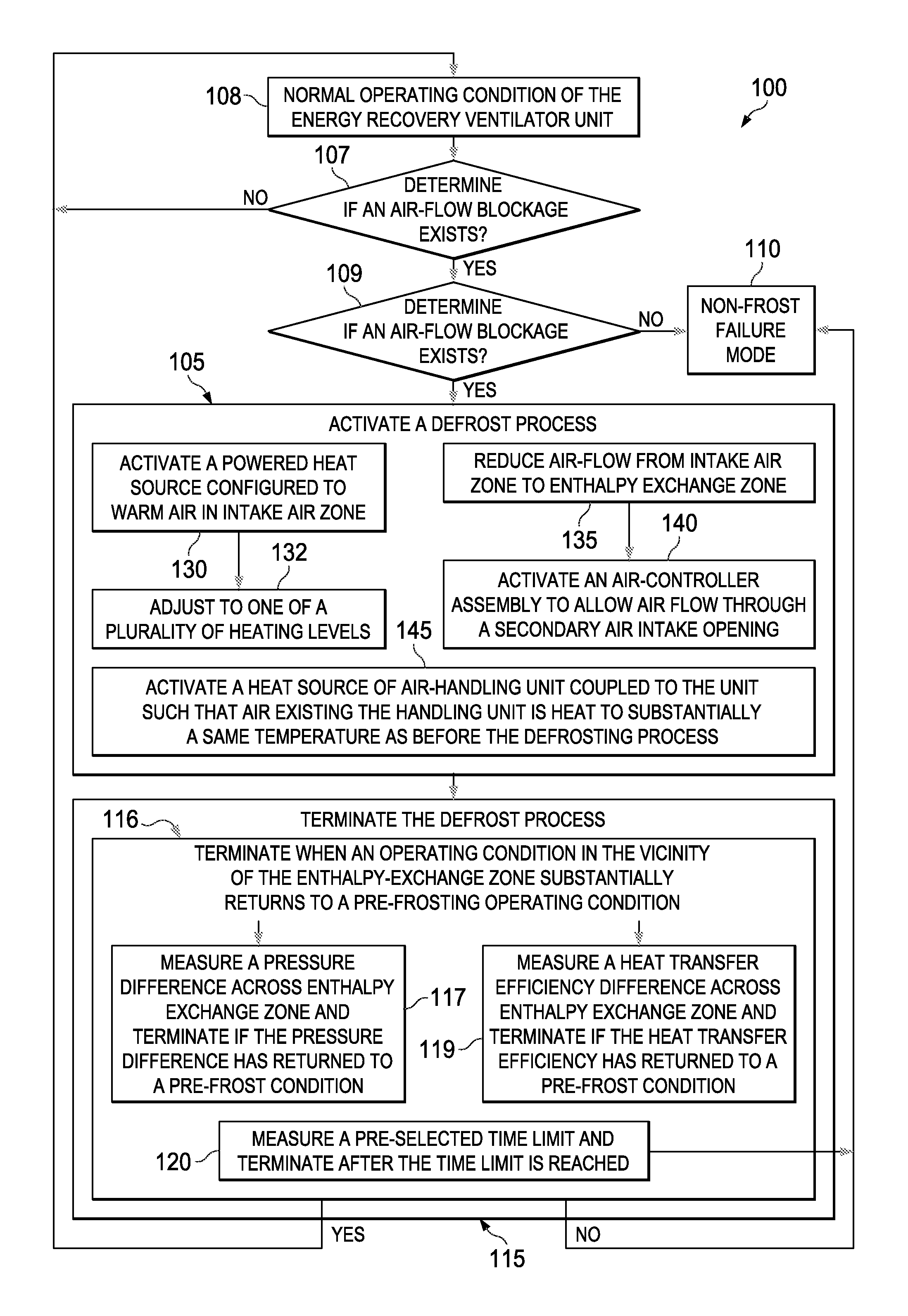
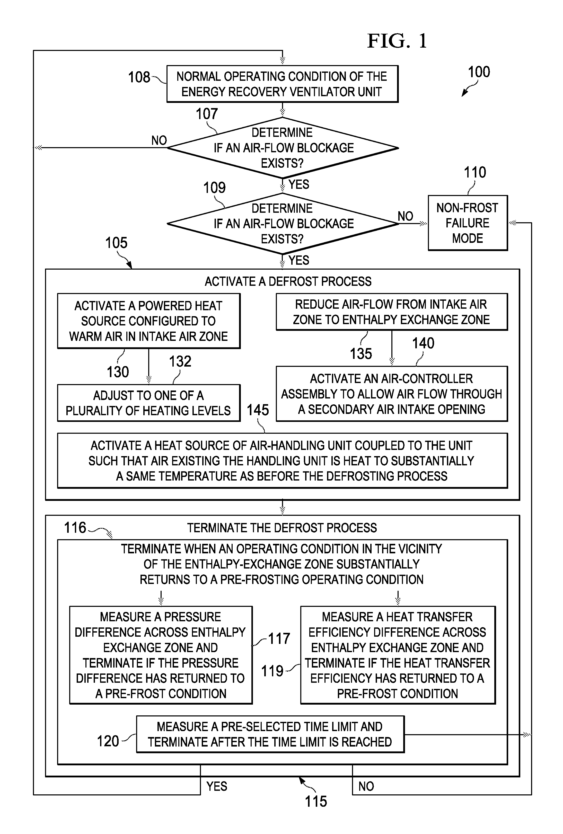
[0014]It is desirable to have an efficient and flexible method for defrosting an energy recovery ventilator unit that both minimizes the energy expended for defrosting and minimizes the time spent when the energy recovery ventilator unit is not in its normal operating mode.

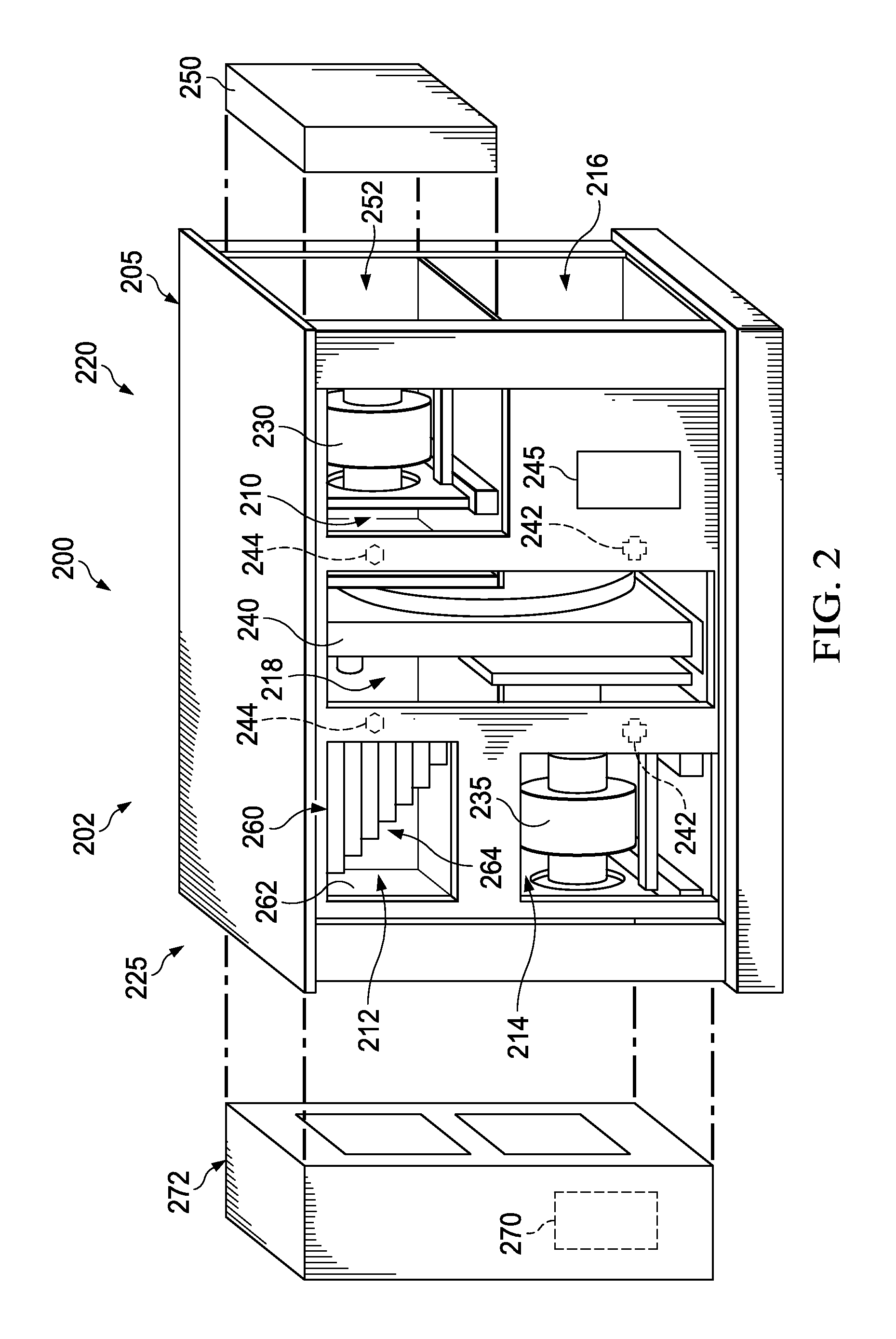
[0015]FIG. 1 presents a flow diagram showing selected steps in an example method of defrosting an energy recovery ventilator unit according to the principles of the disclosure. To facilitate understanding of the flow diagram presented in FIG. 1, FIG. 2 presents a perspective view of an example energy recovery ventilator unit 200 of the disclosure, which can include but is not limited to, any of the design layouts and any of the components pa...


PUM


Abstract

A method of defrosting an energy recovery ventilator unit. The method comprises activating a defrost process of an enthalpy-exchange zone of the energy recovery ventilator unit when an air-flow blockage in the enthalpy-exchange zone coincides with a frost threshold in the ambient environment surrounding the energy recovery ventilator unit. The method also comprises terminating the defrost process, including terminating the defrost process when an operating condition in the vicinity of the enthalpy-exchange zone substantially returns to a pre-frosting operating condition.

Description

CROSS REFERENCE TO RELATED APPLICATIONS[0001]This application is related to U.S. patent application Ser. No. ______ (docket no. P100090), by McKie et al., entitled, “DESIGN LAYOUT FOR AN ENERGY RECOVERY VENTILATOR SYSTEM” (“Appl-1”), filed on Oct. ______, 2011, U.S. patent application Ser. No. 13 / 267,542 (Docket No. P100094), by McKie et al., entitled, “DETECTING AND CORRECTING ENTHALPY WHEEL FAILURE MODES” (“Appl-2”), filed on Oct. 6, 2011, and U.S. patent application Ser. No. 13 / 267,492 (Docket No. P100076), by McKie et al., entitled, “ERV GLOBAL PRESSURE DEMAND CONTROL VENTILATION MODE (ERV CASE)” (“Appl-3”), filed on Oct. 6, 2011, all of which are incorporated herein by reference in their entirety. One or more of the above applications may describe embodiments of Energy Recovery Ventilator Units components and processes thereof that may be suitable for making and / or use in some of the embodiments described herein.TECHNICAL FIELD[0002]This application is directed, in general, to ...

Claims


Application Information

Patent Timeline
IPC IPC(8): F25B47/02
CPCF25B47/02F24F2011/0087F24F11/0086F24F2140/30F24F11/41F24F11/30F24F12/006
Inventor MCKIE, JUSTINPEREZ, ERICTHOMAS, HERMAN MARCUSSCHNEIDER, STEVE
Owner LENNOX IND
Why Eureka
Try Eureka